6 of 13
ARGOS-4 NSHDUxIPx Manual
Version: 1.0 - Date: 01-06-2022
Connections
Wire connection
Connection
Configuration
Penetrator with
CAT cable (4A)
Pin
Connector RJ45
Cable wire
Pin
Connector
RJ45
Cable wire
1
Rx+ (LAN1)(POE+)
Orange/White 4
+Vdc
Blue
2
Rx- (LAN2)(POE+)
Orange
5
+Vdc
Blue/White
3
Tx+ (LAN3)(POE-)
Green /White
7
-Vdc
Brown/white
6
Tx- (LAN6)(POE-)
Green
8
-Vdc
Brown
POE is possible on
the DATA line as
well as on PIN4,5
&7,8
MCBH8MSS
connector (7A)
Mating connector:
MCIL8F* or
MCIL8F-ETH
Pin
MCBH8MSS
Cable wire
Pin MCBH8MSS
Cable wire
1
Rx+ (LAN1)(POE+)
Orange/White
4
nc
Blue
2
Rx- (LAN2)(POE+)
Orange
5
+Vdc 12-72V
Blue/White
3
Tx+ (LAN3)(POE-)
Green /White
7
nc
Brown/white
6
Tx- (LAN6)(POE-)
Green
8
-Vdc 12-72V
Brown
Face view male
POE is possible on
the DATA line and
on Pin 5 and Pin 8
with a voltage
range of 12 to 72
Vdc
*Note: When using the MCIL8F on a CAT cable, use the inline rubber cable of the connector as short as possible when
connecting to the CAT cable. In general we cut the inline cable back to a remaining 15 cm for potting on to the CAT cable.
Interface connection
Connect the camera LAN through a POE injector to your PC. The camera can be powered with POE on the Data lines
and/or with POE on the pin4,5 and pin7,8 for the 4A version, and/or with 12 to 72 Vdc on pin5 and pin8 for the 7A version.
Windows Network setup
You will need to set the PC in the same IP range as the camera by setting the IPv4 to a fixed IP address 192.168.1.1
Windows Network Setup
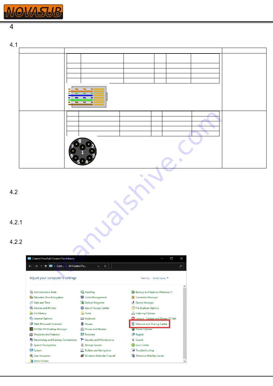
1. Go to the Windows
Control Panel
then select
Network and Sharing Center
. If you do not see Network and
Sharing Center, change the
View by
option to large or small icons.
2. In the Network and Sharing Center window, select
Change adapter settings
.


