background image

NovaLynx Corporation________________________________________________________________________________ 


200-WS-02 

Page 11 

April 2021 


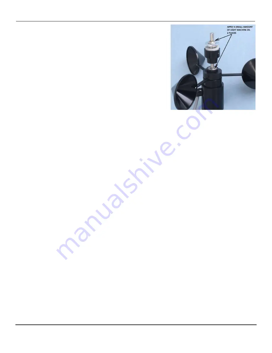
Lubrication 

1.


Apply a tiny drop of light machine oil (e.g. fishing reel oil) to 
the shaft of the potentiometer where it enters the bearing. 
Turn the potentiometer shaft to work the oil into the bearing. 
Do not apply too much oil as it could spread inside the 
potentiometer and contaminate the resistance material.


2.


Apply a few drops of light machine oil to the top of the ball 
bearing that supports the cup assembly. Spin the cup 
assembly to work the oil into the bearing.


3.


Wipe excess oil off of the bearing and potentiometer shaft.


Test and Balance 

1.


Perform the Anemometer Electrical Test (Section 11.1). The test will confirm that the reed switch 
responds to the magnets when the cup assembly rotates. 

2.


Perform the Potentiometer Electrical Test (Section 11.2). This test will ensure the electrical output 
of the direction sensor is working. The procedure includes information on how to align the vane 
with the potentiometer. Install the vane according to the instructions. 

3.


The final step is to balance the wind vane. Hold the base of the sensor and turn it sideways so that 
the sensor is horizontal to the ground. If the vane is balanced it should show no tendency to rotate. 
If it is not balanced either the counterweight or tail will rotate downwards. If the vane is out of 
balance, loosen the vane set screw (Figure 1) and slide the vane either forwards or backwards to 
balance the vane. Don’t forget to align the tail with the vertical axis while you tighten the set screw. 

11


FUNCTIONAL TESTS 


The following checks can be done with an ohm-meter after the sensor has been removed from the 
tower or tripod. These tests can help determine whether the sensor needs repair or adjustment. 

11.1


Anemometer Electrical Test 


Set the ohm-meter to a low resistance range and touch its leads together to check for zero ohms. If it is 
an analog meter adjust the dial to read zero ohms. Connect the meter to the wind speed output signal 
wire and ground wire. 

Rotate the cup assembly slowly until you notice the meter reading drop to less than 10 ohms. Continue 
to rotate until the switch opens (high resistance). Do this for each of the 3 magnets in the cup 
assembly. If the meter always reads a low resistance then the reed switch is not opening (the contacts 
may have welded together) or there may be a short circuit in the cable. If the switch never closes then 

Содержание 200-WS-02 Series

Страница 1: ...DOC 200 WS 02 UM 20210413 200 WS 02x User Manual WeatherPort Wind Speed and Direction Sensors 200 WS 02E 200 WS 02F Phone 530 823 7185 Email nova novalynx com Website www novalynx com...

Страница 2: ...ns in the case of delicate or sensitive items If packing facilities are not available take the equipment to the nearest Post Office UPS or other freight service and obtain assistance with the packagin...

Страница 3: ...ON 4 3 PRECAUTIONS 5 4 SPECIFICATIONS 5 5 SITE SELECTION 6 6 TAIL ASSEMBLY 6 7 MOUNTING OPTIONS 7 8 INSTALLATION 8 9 WIRING DIAGRAMS 9 10 MAINTENANCE 10 10 1 General Inspection 10 10 2 Lubrication and...

Страница 4: ...arts a rotating cup style anemometer for measuring wind speed and a wind vane for measuring horizontal wind direction Wind Speed Measurement Air movement wind causes the cup and hub assembly to rotate...

Страница 5: ...max Speed Threshold 1 2 mph 0 54 m s Speed Constant 1 25 mph 1 Hz 0 5588 m s 1 Hz Accuracy 1 mph 0 4470 m s or 3 Transducer Type Reed switch magnet activated Maximum Rating 10 mA 50 V ac or dc Turning...

Страница 6: ...e building and away from all exhaust vents If the sensor is located on top of a building the sensor height should be 1 5 x H where H is the height of the building In all cases when the wind sensor dat...

Страница 7: ...aLynx tripods are a convenient alternative for temporary and permanent installations The tripods are available in three sizes 3 5 and 10 tall Appendix A Masts are available in various lengths Swaged m...

Страница 8: ...erate torque The PVC jacket of the cable will last for many years outdoors under normal circumstances In harsh environments it may be necessary to protect the cable with conduit Route the sensor cable...

Страница 9: ...CCW CW S 355 ELECTRICALANGLE 3 PER REV Earth Ground Clear Black Red Green White Reed Switch 20k ohms Signal Ground Vref Direction Signal Speed Signal DWG 890 0023 04 200 WS 02E Wind Speed and Directio...

Страница 10: ...ts 4 Inspect the counterweight to ensure it is firmly cemented to the vane Repair if necessary 5 Inspect the wind vane to ensure the tail is vertical and the screws holding it to the vane are snug 6 I...

Страница 11: ...wind vane Hold the base of the sensor and turn it sideways so that the sensor is horizontal to the ground If the vane is balanced it should show no tendency to rotate If it is not balanced either the...

Страница 12: ...ance changes smoothly from near zero to the maximum just before hitting the dead band again as you approach north If the dead band does not align with the NORTH label then the position of the vane can...

Страница 13: ...NovaLynx Corporation 200 WS 02 Page 13 April 2021 APPENDIX A TRIPOD DIMENSIONS...

Отзывы: