background image

Page 20 of 35 


7.  Move the auxiliary hydraulics lever forward, backward, and back to the neutral position to relieve 

hydraulic pressure at the hydraulic couplers.  

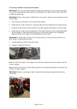
8.  Remove protective covers from the hydraulic couplers on the machine. Connect covers together 

to prevent contamination during operation. 

9.  Insert hydraulic connectors from attachment i

nto the machine’s couplers.  Note – female 

connector is connected onto male adaptor and male connector is inserted into female coupler.  

10.  Confirm that the connections are secure by pulling on the hoses.  

Disconnecting  

1.  Lower the attachment onto a firm, level surface.


2. 

Shut off the machine engine.


3.  Move the auxiliary hydraulics lever forward, backward, and back to the NEUTRAL position to 

relieve hydraulic pressure at the hydraulic couplers. This step can be disregarded if the bucket or 
attachment does not utilize the hydraulic connectors. 

4.  Slide the collar back on the hydraulic coupler to release the connection and pull back on the 

attachment’s couplers to disconnect the attachment couplers from the machine couplers. 

Note:

 If 

collars are difficult to move, repeat step 3. 

IMPORTANT:

 Connect the attachment hoses together to prevent contamination during storage.  

5.  Re-Install protective covers onto the machine

’s hydraulic couplers.  

6.  Disengage the attachment lock pins by turning them to the outside.  

7.  Start the engine, tilt the mount plate forward, and back the machine away from the attachment. 

After Each Use 

Transporting and Securing 

IMPORTANT

: When transporting the machine on a trailer, always use the following procedure.  

1.  Lower the loader arms.  

2.  Reduce engine speed to idle and Turn the ignition key to OFF to stop the engine.  

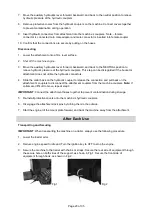
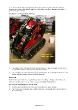
3.  Secure the machine to the trailer with chains or straps. Secure the rear side of equipment through 

the secure hole on both sides of the support, as shown in Fig 1. Secure the front side of 
equipment through hook, as shown in Fig 2.  

 Fig 1              

 Fig 2 


Содержание 20 HP Mini-Track Gas Loader

Страница 1: ...ni Track Gas Loader Owner s Manual WARNING Read carefully and understand all OPERATING INSTRUCTIONS before operating Failure to follow the safety rules and other basic safety precautions may result in...

Страница 2: ...come familiar with this product before you begin using it This 20 HP Mini Track Gas Loader is designed for certain applications only Northern Tool and Equipment is not responsible for issues arising f...

Страница 3: ...nical Specifications 4 Important Safety Information 4 Safety and Product Labels 9 Before Each Use 10 Operating Instructions 13 After Each Use 20 Maintenance 21 Troubleshooting 30 Parts Diagram 32 Part...

Страница 4: ...Hinge Pin 73 5 in 1867 mm Specifications and design subject to change without notice Important Safety Information WARNING Read and understand all instructions Failure to follow all instructions may r...

Страница 5: ...ep your hair clothing and gloves away from moving parts Loose clothes jewelry or long hair can be caught in moving parts Air vents on the tool often cover moving parts and should be avoided Wear the p...

Страница 6: ...iar with the safe operation of the equipment operator controls and safety signs All operators and mechanics should be trained The owner is responsible for training the users Never let children or untr...

Страница 7: ...bystanders away Slow down and use caution when making turns and crossing roads and sidewalks Do not operate the machine when you are tired ill or under the influence of alcohol or drugs Use care when...

Страница 8: ...ion changes An empty bucket will make the rear of the loader unit the heavy end and a full bucket will make the front of the loader unit the heavy end Most other attachments will make the front of loa...

Страница 9: ...d Hazard Warning Decal 3 5 Crush Hazard Hand Track Warning Decal 2 6 Fire Hazard Danger Decal 1 7 Rotating Parts Warning Decal 1 8 Crush Hazard Body Access Panel Warning Decal 1 9 Operational Warnings...

Страница 10: ...of objects and structures that may not be marked such as underground storage tanks wells and septic systems Read this manual and the engine s manual before operating Always check the following before...

Страница 11: ...way from electrical appliances Important Do not high pressure wash High pressure washing can damage the electrical system Adding Fuel WARNING Use extra care when handling fuels They are flammable and...

Страница 12: ...fer to the engine operating manual for oil specifications 2 Remove any debris from the machine and clean around the dipstick and oil fill location 3 With the engine cold and the machine parked on a le...

Страница 13: ...n of the machine before beginning operation This inspection should include Check all decals and warning signs for damage Check all fuel oil and hydraulic lines hoses fittings and connections for signs...

Страница 14: ...sult in loss of control Do not overload the attachment and always keep the load level when raising the loader arms Logs boards and other items could roll down the loader arms injuring you Never jerk t...

Страница 15: ...ngine starts gradually move the choke inward If the engine stalls or hesitates pull the choke out again until the engine warms up When starting the engine in cold conditions allow the engine to run in...

Страница 16: ...the loader arm Back Raise the loader arm Right Dump bucket Tilt attachment forward Left Curl bucket Tilt attachment backward Throttle Lever Lever 2 Push forward to increase engine RPM and pull backwar...

Страница 17: ...he faster the machine will move in that direction To turn decrease the pressure on the drive control lever closest to the direction you want to turn To slow or stop move or release the drive control l...

Страница 18: ...ing Light Switch Press the switch and the working light will turn on Attachments To use optional attachments the bucket must first be removed Disconnecting the Bucket or Optional Attachments 1 Lower t...

Страница 19: ...te 4 Slowly raise the loader arms by pulling back on the loader control lever while curling tilting back the mount plate by moving the loader control lever to the left at the same time to engage the a...

Страница 20: ...e hydraulic connectors 4 Slide the collar back on the hydraulic coupler to release the connection and pull back on the attachment s couplers to disconnect the attachment couplers from the machine coup...

Страница 21: ...lifting points and move the machine Maintenance WARNING Disengage the auxiliary hydraulics lower the attachment stop the engine and remove the key Wait for all movement to stop and the unit to cool b...

Страница 22: ...devices Keep the loader unit free of grass leaves or other debris build up Clean up oil or fuel spillage Allow the loader unit to cool before storing Use extra care when handling fuels They are flamm...

Страница 23: ...ir to clean or Replace the air cleaner Check the fuel lines and clamp bands Tighten or replace as needed Check the engine s oil level Fill to proper level as needed Every 100 hours Change engine oil a...

Страница 24: ...nts of the lift arms 2 These bushings are wear part and require regular inspection Worn bushings should be replaced to avoid damaging loader arms and related components Engine Oil Refer to the engine...

Страница 25: ...tighten to engine manufacturer s specified torque Note Properly dispose of dirty oil filter and used engine oil 7 Refill engine crankcase Slowly pour approximately 80 of the specified amount of oil r...

Страница 26: ...ion Replace hose clamps to their correct position to secure the fuel lines to the filter 6 Remove the clamp blocking the fuel flow or return the fuel shut off valve to the OPEN position Fuel Tank Drai...

Страница 27: ...and drain completely into an approved fuel container by tipping the tank upside down Clamp the fuel line and flush the tank by pouring a small amount of clean fuel into the tank and swirling around to...

Страница 28: ...e bottom of the hydraulic tank and allow the fluid to completely drain out 5 Remove the old filter and wipe the filter adapter gasket surface clean 6 Apply a thin coat of hydraulic fluid to the rubber...

Страница 29: ...ean and fully charged Use a paper towel to clean the battery case If the battery terminals are corroded clean them with a solution of four parts water and one part baking soda Apply a light coating of...

Страница 30: ...emoved from the engine spray and appropriate engine fogging oil into the spark plug hole Now use the starter to crank the engine and distribute the oil inside the cylinder Install the spark plug s Do...

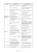
Страница 31: ...he NorTrac Technical Service department Engine loses power 1 Engine load is excessive 1 Reduce ground speed 2 Air cleaner is dirty 2 Clean the air cleaner element 3 Oil level in crankcase is low 3 Add...

Страница 32: ...fective or damaged 4 Inspect and repair or replace as needed Contact the NorTrac Technical Service department for parts assistance 5 Control valve is defective or damaged 5 Inspect and repair or repla...

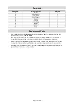
Страница 33: ...nical Support at 1 800 521 0438 Not all product components are available for replacement The illustrations provided are a convenient reference to the location and position of parts in the assembly seq...

Страница 34: ...rization from NorTrac Warranty Administrator and the address of the pre authorized service center take the equipment to the service center during their regular business hours All transportation costs...

Страница 35: ...Page 35 of 35 Distributed by Northern Tool Equipment Company Inc Burnsville Minnesota 55306 www northerntool com Made in China...

Отзывы:

Похожие инструкции для 20 HP Mini-Track Gas Loader