background image


Assembly Instruction - 

nortik scubi 1 XL


Dear customer, 
 
You  have  purchased  a 

nortik  scubi  1  XL

  –  an  innovative  hybrid  kayak  for 

recreational use. With great performance, little packing size and weight for a boat of 
this size, it is extremely versatile in use. 
 
The  assembling  instructions  are  very  detailed  and  almost  every  step  is  illustrated. 
You will notice that it will help you at one point or another. After a few times and with 
a little practice you won’t need the manual anymore. 
 
The  experience  shows  that  the  first  assembly  needs  more  time  than  you  will  need 
later and we ask you to assemble the boat step by step according to this instruction. 
After  some  practice,  you  will  assemble  the 

nortik  scubi  1  XL

  easily  within  15 

minutes! 
 
 
Please note that there is an assembly video on youtube: 

https://www.youtube.com/faltboot_de


Each boat is assembled and checked before it leaves the factory. Should you believe 
that something is wrong with your boat, please contact us quoting the serial number. 
The serial number is located on a label inside the hull. 
 
 
If  you  have  any  questions,  your  dealer  will  be  happy  to  assist  you.  Otherwise,  you 
can  also  contact  us  directly  -  as  an  importer  (call:  0049/731/4007675,  mail: 

[email protected]

). 


Содержание scubi 1 XL

Страница 1: ...Assembly instructions nortik scubi 1 XL Recreational kayak V2 2016 QR Code assembly video ...

Страница 2: ... the first assembly needs more time than you will need later and we ask you to assemble the boat step by step according to this instruction After some practice you will assemble the nortik scubi 1 XL easily within 15 minutes Please note that there is an assembly video on youtube https www youtube com faltboot_de Each boat is assembled and checked before it leaves the factory Should you believe tha...

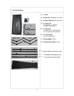
Страница 3: ...al 2x center identical 5 4x Keel rod 2x identical 1x hemispherical end 1x with riveted half tube 6 3x Foam pad keel reinforcement 7 Packing Bag no pic 8 Double action pump no pic 1 2 3 4 5 6 Bow Stern Steven Bow stern center 2x identical keel rod open at each side 1x keel rod with riveted half tube 1x keel rod with hemispherical end ...

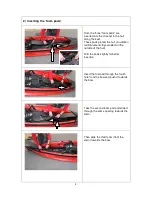
Страница 4: ...ll in addition reinforcement strips welded on the outside of the hull Fold the pads slightly for better insertion Insert the first pad through the fourth hole from the bow and push it towards the bow Take the second foam pad and slide it through the same opening towards the stern Then slide the third foam from the stern towards the bow ...

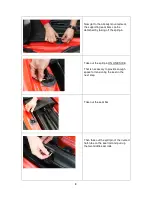
Страница 5: ...ds and the keel rod with the hemispherical end Insert the bow element as far as possible into the bow Then push the keel rod with the open end through the sleeve and clip it onto the bow element Bow element 1x keel rod with hemispherical end 1x keel rod open at each side sleeve ...

Страница 6: ...e hull under the seat towards the bow and clip it onto the previously installed keel rod 4 Assembly of the stern You need the stern element one of the two identical rods and the keel rod with the riveted half tube sleeve 1x keel with riveted half tube 1x keel rod open at each side Stern element Steven ...

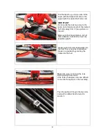
Страница 7: ...l rod with the open end through the sleeve towards the stern and clip it onto the stern element Take the keel rod with the riveted half tube lead it under the seat and clip it onto the rod you just installed NOTE Make sure the open part of the riveted half tube points downwards sleeve ...

Страница 8: ...hed by taking off the split pin Take out the split pin ON ONE SIDE That is necessary to provide enough space for tensioning the keel in the next step Take out the seat bar Then take out the split pin of the riveted half tube on the keel rod and pull up the two middle keel rods ...

Страница 9: ... Make sure that bow and stern do not twist sidewise but stand as much as possible upright Slowly push both rods downwards into the hull This is how the longitudinal tension is provided by pressing the frame into the hull Make also sure not to twist the rods while pushing them down If the rods are twisted it can be difficult to re enter the split pin in the next step Push the split pin through the ...

Страница 10: ...he pin Now the two identical cross ribs are installed behind and in front of the seat Push the boat skin a bit aside and place the cross rib in front of the seat diagonally onto the clip on the keel rod see picture on the left Then right it slowly up while the clips interlock ...

Страница 11: ...s rib sits upright clip in the seat bars on the back side of it see picture Note If this is hard to do slide the seat cloth as far as possible towards the stern Proceed likewise with the other cross rib behind the seat ...

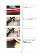
Страница 12: ...gs mounted on each side of the hull Proceed likewise on the other end Now inflate the high pressure sponsons Best is first to inflate the lower sponson on one side to around 50 then on the other side equally Then change again and fully inflate them in turns Proceed likewise with the upper sponsons Then insert the adapter into the valve and with a half turn screw it to it ...

Страница 13: ...t you can adjust by pushing and turning the white pin in the middle In one position you can inflate and disconnect the pump without letting the air out again If you want to deflate push in the pin and do a half turn The valve stays open The ideal pressure is 0 25 0 35 bar 3 63 5 07psi Do not exceed it Your boat is now fully assembled and ready for use ...

Страница 14: ...3 put the spacer through the hole Then screw the wing nut back on again Extensions for the steering ropes Steering bar Rudder blade 2x Shackle for steering bar Carabiner for pull up rope 1x Pull up rope the shortest 2x Steering rope Camp fixation for the pull up rope with Velcro Clip for pull up ropes Spacer 2x Tube for steering rope ...

Страница 15: ...p rope through the clamp Then lead the cord through the two parts of the fastening clip as shown on the picture Run it back through the fastening clip and then slide the one part of the clip into the other part as shown on the picture The clip is later on used for easier pulling up the rudder blade ...

Страница 16: ...t Then lead the two steering ropes through the holes in the cross beam of the rudder system as shown on the picture and loop it back around the end of it Then attach the extension cords to the D rings under the cover in the bow in a similar way as shown on the pictures ...

Страница 17: ...D rings in the bow Now place the two tubes for the steering ropes onto the Velcro in the stern as shown on the picture Lead one steering rope through each of them towards the bow and then lead them through the stainless D Rings of the knee rests ...

Страница 18: ...e extension s chain This gives you the possibility to vary the position of the chain to suit your leg length Then position the steering bar to the desired position and secure it with the two shackles Attach the pull up rope to the rudder blade with the carabiner ...

Страница 19: ... in reverse order Drain the air completely from the hull by using the deflate function of the pump Then fold the sides longitudinally to the center In the result you should only be seeing the black hull material from above Fold it like shown on the next pictures ...

Страница 20: ...20 ...

Страница 21: ...ut air in case the pressure exceeds too much It is a security mechanism for the extreme case Do not test it willingly but follow the guidelines You can store your nortik scubi 1 XL built up or disassembled in the bag Please make sure that your boat is not exposed to unnecessarily long heat If it is built up take thepressure from the sponsons by deflating them a bit Repairing and reinforcements The...

Страница 22: ...22 Further information about your and other products and sources of supply and downloads are available at any time to ...

Отзывы: