Specifications subject to change
TECHNIC
TECHNIC
TECHNIC
TECHNIC
TECHNICAL BULLETIN
AL BULLETIN
AL BULLETIN
AL BULLETIN
AL BULLETIN
Headquarters:
5007 S. Howell Ave.
Milwaukee, WI 53207 USA
Tel: +1 (414) 769-5980
Fax: +1 (414) 769-5989
or +1 (414) 769-5996 (Int’l)
Northern Computers, Inc.
Worldwide Locations:
•
Crawley, Sussex, United Kingdom
Tel: (44) 1293-592700 • Fax: (44) 1293-523061
•
Sao Paulo, Brazil
Tel: (55) (11) 826-4944 • Fax: (55) (11) 826-0649
•
Australia
Tel: (612) 9699-3700 Fax: (612) 9699-3101
•
Hong Kong
Tel: 852-2528-1897 • Fax: 852-2528 4599
•
Montreal, Quebec, Canada
Tel: 514-933-3363 • Fax: 514-933-3447
•
Moscow, Russia
Tel: (7) 095-723 2626 • Fax: (7) 095-956 5428
•
France
Tel: 33-1-30-13-03-93 Fax: 33-1-3- 13-03-90
•
Mexico
Tel: (52) (5) 280-7890 Fax: (52) (5) 280-8555
•
Ecuador
Tel: (593) (2) 265-588/91 Fax: (593) (2) 461-379
July 1998; Rev. 2.1 (page 1 of 2)
KP-13 Keypad Wiring Instructions
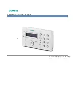
The KP-13 Keypad is a 5-wire Wiegand output keypad suitable for outdoor use. It is wired to a control
panel in the same manner as a card reader (see figure 1). The KP-13-ILL is the same keypad with illumina-
tion.
The KP-13 uses the 32-bit Wiegand format: _F=pn_2_32_S_0_D_0_B1_B2_B3_B4 (required for N-1000
with 4.17 or older firmware).
This format can be entered in a text file or Terminal Mode (not required for N-500). Refer to panel installa-
tion and programming manuals for more information. As with all keypads, press the “#” key after code
entry. To clear an entry, press the “
*
” key. To toggle illumination off and on (KP-13-ILL only), press “
*
” and
“3” at the same time.
LED Operation.
When the reader is first powered up, the green LED will remain on until after the first
valid card read. When the “M” option is enabled in the panel programming the LEDs operate as follows:
●
Normally, the red LED is on.
●
Upon valid code entry, the green LED comes on and the red LED goes off.
●
After the LED pulse time elapses, the green LED goes off and the red LED comes on.
●
Upon invalid code entry, no LED change occurs.
Grounding.
The tan wire is a chassis ground. If the keypad is mounted directly on grounded metal, tie the
tan wire to the grounded metal. Tie the keypad cable shield to the control panel ground point and float
shield at keypad. If the keypad is mounted on ungrounded metal or nonmetallic material, tie the tan wire to
the keypad cable shield and connect the shield to the control panel ground point.
Wiring specifications
NCI Part #
Description
Maximum Distance
NC1861/BL
6-wire 18 AWG shielded
500 feet
TD2006
Figure 1. Wiring for the KP-13.
Power for the keypad can be
supplied from the control panel.
KP-13
Black
(Common)
Red
(+5VDC)
Green
(Data 0)
White
(Data 1)
Brown
Tan
(Earth Ground)
The Blue wire remains disconnected (not used)
(LED)


