


D/S One/Two Channel (Modules 1*, 2*, 3*, 4*)
75DS2 Operations Manual
North Atlantic Industries, Inc.
11/11/2011
Rev: 2011-11-11-1000
www.naii.com
Page 13 of 43
D/S Rotation
Each channel may be configured for either start/stop or continuous rotation for applications that require it. In
start/stop mode, the user can program a rotational velocity and a stop angle. When triggered, either via a software
command or external pulse (selectable trigger mode), the output signal will start at the current position and
simulate rotation at the specified rotation rate and stop at the programmed stop angle. Re-initiating the trigger will
repeat the rotation. In continuous mode, the user will program a rotation rate and trigger the start of the rotation
either via software command or external trigger. Stopping rotation can be accomplished by either issuing a stop
rotation command or setting a commanded angle. Clockwise or counter-clockwise rotation is accomplished by
setting either a p
ositive or negative 2’s complement word in the velocity register.
Note:
Writing to an Input Angle
Register will stop any rotation initiated on that channel.
D/S Stop Angle
May be used during implementation of D/S rotation. When the channel is set for start/stop rotation (
D/S Rotation
Mode
register), write the desired stop angle to this register. Write a 16-bit integer (or 16-
bit 2’s compliment
integer) to the corresponding channel
D/S Write Angle
register. (ex. 330
= EAABh).
WORD = (Angle
(360/2
16
)).
D/S Set Rotation Rate
May be used during implementation of D/S rotation. Write to the corresponding
Set Rotation Rate
registers (Hi
and Lo) a 2’s complement number representing the desired rotation rate, LSB = 0.015
/sec.
Ex:
12 RPS = (12 x 360
/0.015
= 288000 = 46500h), -12 RPS = (-12 x 360
/0.015
= -288000 = 0xB9B00h)
Step size is 16 bits (0.0055
) for up to 1.5 RPS, and then linearly decreases to 12 bits (0.088
) at 13.6 RPS.
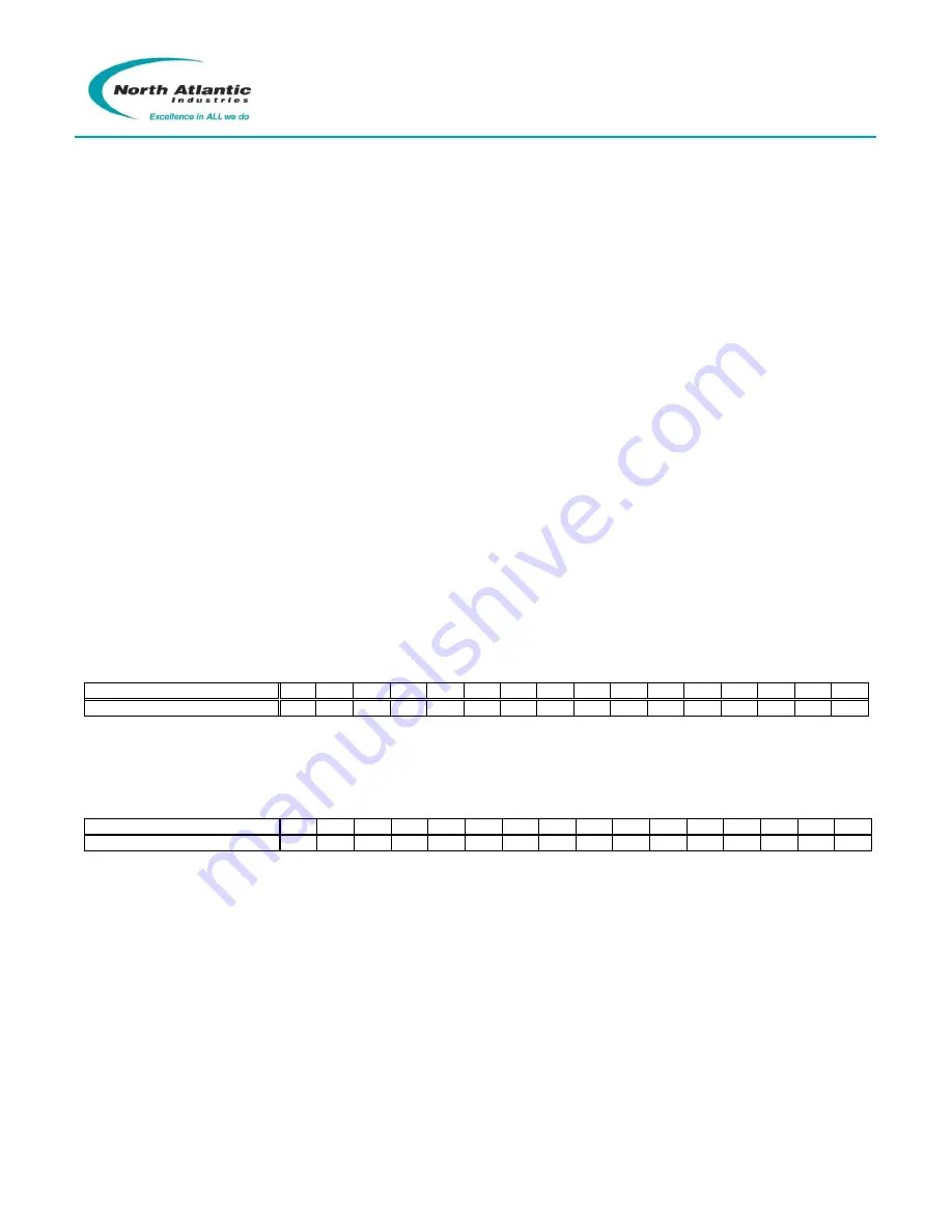
D/S Rotation Mode, Continuous or Start/Stop
For continuous rotation, set the corresponding channel bit to "0" in the
Rotation Mode
register. For rotation to
cease at a designated stop angle, set the bit to "1". For 2-speed applications, only the odd (coarse) channel
needs to be programmed (CH1).
D15
D14
D13
D12
D11
D10
D9
D8
D7
D6
D5
D4
D3
D2
D1
D0
D/S Rotation Mode
X
X
X
X
X
X
X
X
X
X
X
X
X
X
CH2
CH1
D/S Rotation Status
Check the corresponding bit of the
D/S Rotation Status Register
for condition of rotation (
“Done” or “Not Done”)
for each
channel. A ”1” means Rotation Done (output is static), “0” means Rotation Not Done (output is rotating)
on channel. Rotation monitoring is always enabled.
D15
D14
D13
D12
D11
D10
D9
D8
D7
D6
D5
D4
D3
D2
D1
D0
D/S Status, Rotation
X
X
X
X
X
X
X
X
X
X
X
X
X
X
CH2
CH1
Start Rotation
Implements a software command to initiate rotation (
D/S Trigger Source Select Register
is set for “internal”). First
set the
Rotation Rate
and
Rotation Mode Registers
for each channel that is to rotate. Then, to start rotation for the
corresponding channel, write a “1” to the corresponding channel
D/S Start Rotation register
.
Stop Rotation
To stop rotation for the corresponding channel, write a “1” to the corresponding channel
D/S Stop Rotation
register. Channel will remain at the stopped angle until new input angles are set, or rotation is again initiated.
Note:
An in-process rotation can also be stopped by commanding a new angle (
D/S Write Angle
).


