Nortec RESDELUX Скачать руководство пользователя страница 6

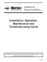
STEAM HOSE INSTALLATION

1.

The length of the steam hose must not exceed 4’
(1.2m).

2.

It must not be restricted in any way (i.e. - a kink
resulting from a short radius bend).

3.

Avoid condensate traps in the hose, see Figure
#8.

4.

Use wall clips (p/n 158-5001) to support the
steam and condensate hoses and maintain 1”
clearance from the wall. The connection can also
be made with ¾” copper pipe with 1” thermal
insulation rated for 215

°

F (101°C).

CONDENSATE HOSE (supplied)

Under normal circumstances, when the steam

distribution nozzle is above the top surface of the
humidifier, the condensate hose is routed back to the
top of the humidifier and fed through the opening
provided to the fill cup. Cut the ends diagonally and
simply insert ½" in the appropriate hole in the top of
the humidifier. Install a 3/8” copper tubing trap at the
lowest point in the condensate system. Connect to the
hose with a clamp Figure #6.

BLOWER PACK CONNECTION

The RESDELUX humidifier can be purchased with

an optional blower pack for direct room humidification.
The blower pack is field installed on the RESDELUX
humidifier cabinet or located remote from the
RESDELUX humidifier.

The blower pack is powered directly from the

RESDELUX control board. It cannot be powered
separately.

On a call for humidity, blower fans are powered

and remain powered for about two minutes after steam
production is interrupted.

Cabinet Mounting of the Blower Pack

The RESDELUX blower pack comes with a basic

hardware kit. The kit contains all the hardware
required to cabinet mount the blower pack.

NOTE: Mounting of the blower pack must be

performed before the RESDELUX humidifier is
installed and wired.

1.

Remove the RESDELUX humidifier and blower
pack from their shipping boxes.

2.

Place the RESDELUX humidifier upright on a flat
surface.

3.

Remove the 7/8” knockout on the top of the
RESDELUX humidifier. There are two
knockouts, select the one closest to the large
opening.

- 3 -

To be 2” (50mm) longer

then duct static pressure

or minimum.

6”

min

(150

mm)

12”

(300

mm)

12”

(300

mm)

min. 2º

min. 10º

min. 10º

12”

min.

(300

mm)

Rmin

.

min. 10º

min. 2º

min. 20 %

min. 20 %

12”

(300

mm)

12”

(300

mm)

6”

min

(150

mm)

12”

min.

(300

mm)

6”

min

(150

mm)

Nortec Humidifiers

All Models

Nortec Humidifiers

All Models

Figure #7

Steam Plumbing Arrangement Below Humidifier

Avoid Water Traps

Avoid kinks

Proper
Slope

Gentle
Sweeping
Turns

Figure #8

Steam Hose Routing

Содержание RESDELUX

Страница 1: ...RESDELUX Steam Humidifiers Installation Operation Maintenance and Troubleshooting Guide IMPORTANT READ AND SAVE THESE INSTRUCTIONS This guide to be left with equipment owner 1505691 B ...

Страница 2: ...AL REQUIREMENTS FOR PERMANENTLY CONNECTED RESDELUX 6 ELECTRICAL REQUIREMENTS FOR THE CORD CONNECTED MODEL RESDELUX C 6 LOW VOLTAGE CONTROL WIRING AND INSTALLATION 6 CONTROL WIRING 6 CONTROL INSTALLATION 7 OPERATION 7 INTRODUCTION 7 RESDELUX OPERATION 7 MANUAL CAPACITY ADJUSTMENT 8 OTHER POTENTIOMETERS 8 MAINTENANCE 8 STEAM CYLINDER 8 WHEN TO REPLACE THE STEAM CYLINDER 8 HOW TO REMOVE THE STEAM CYL...

Страница 3: ... DRAIN TIME 12 RATED AMPERS 12 SHORT CYCLING 12 FOAMING 12 BACKPRESSURE 12 MONITORED LEG 12 RESDELUX WIRING DIAGRAM 13 SUGGESTED WIRING INTERFACE FOR FAN CONTROL 14 SPARE PARTS LIST AND EXPLODED VIEW 15 16 PERIODIC MAINTENANCE CHECKLIST 17 ...

Страница 4: ...ward LOCATION MOUNTING HUMIDIFIERS RESDELUX Series humidifiers are designed to mount on a suitable wall or vertical surface Do not sit on the floor due to additional clearances required for plumbing electrical and control access holes The clearance dimensions shown in this manual are for reference only and are the minimum required for maintenance of the humidifier Local and National Codes should b...

Страница 5: ... above the top surface of the humidifier The nozzle must be at least 1 ft 305 mm above the top surface of the humidifier Locate the steam hose so that it slopes at an angle of at least 20 Figure 6 4 Steam distribution nozzle below top surface of humidifier The steam hose must first rise to the minimum height of 1 ft 305 mm above the top surface of the humidifier and thereafter slope a minimum 5 in...

Страница 6: ...ifier cabinet or located remote from the RESDELUX humidifier The blower pack is powered directly from the RESDELUX control board It cannot be powered separately On a call for humidity blower fans are powered and remain powered for about two minutes after steam production is interrupted Cabinet Mounting of the Blower Pack The RESDELUX blower pack comes with a basic hardware kit The kit contains all...

Страница 7: ...at it is unplugged RESDELUX C 3 Find a suitable location for mounting the remote blower pack The surface should be flat with adequate clearances for the top side and front 4 Minimum slope of steam hose is 20 Steam lines longer than 5 ft require condensate trap installation see Figure 6 5 RESDELUX blower pack has two teardrop or keyhole openings on the back of the cabinet for mounting purposes They...

Страница 8: ... could become plugged 4 ALWAYS supply and install a shut off valve in the water supply line dedicated to the humidifier to facilitate servicing Use O D copper to within 4 feet of the humidifier Reduce copper to 1 4 O D and connect to the factory supplied 1 4 olive compression fitting under the humidifier DRAIN LINE 1 The humidifier is equipped with a 7 8 O D unthreaded horizontal drain outlet from...

Страница 9: ......

Страница 10: ...esentative of overall space being humidified and not in the path of the blower pack or air supply grille Do not mount on an outside wall where temperature fluctuation can affect the control response 2 Duct Humidistat Mount the duct humidistat In a location representative of overall air humidity usually the return duct Do not mount it directly in front of the steam distributor or in a turbulent or ...

Страница 11: ...TMENT The RESDELUX humidifier is rated in lbs hr of steam output capacity Set to 100 it will operate at full output until the humidistat has sensed that the humidity has reached setpoint it will then stop when the control circuit 1 2 is interrupted See Figure 13 If the humidifier is oversized the humidistat will be quickly satisfied less then 10 minutes and stop the humidifier As the humidity leve...

Страница 12: ...it 5 Open the front cover door 6 Cylinder plugs are attached to the primary voltage cylinder wires Remove cylinder plugs from cylinder pins by pulling vertically 7 Using a slotted screwdriver loosen the steam hose clamp s and pull the steam hose off the cylinder vertically 8 The cylinder is now ready to be lifted out of the unit CAUTION Cylinder and any undrained water might still be HOT 9 Remove ...

Страница 13: ... valve port 8 The tapered end of the spring must be installed toward the solenoid Reassemble and tighten the actuator 1 4 turn past hand tight 9 Clean out the end of the hose then reconnect it to the drain valve body with the clamp 10 Inspect the o ring to make sure it is in good condition 11 Fit mounting screws through the drain valve body one through the ring terminal on green ground wire 12 Pus...

Страница 14: ...his may take a day or two Off Off No power to the board Check for main power supply fault Turn power switch to Drain position If drain valve is activated sound of solenoid check connection to the board or board itself When no sound present check fuse replace with 1 5A if needed transformer voltage should be present between fuse holder and ground screw 1 flash sequence Off Over current Operating am...

Страница 15: ...nual drain time with and without the external drain connected Is the external drain impeding flow NORTEC recommends an open external drain line See the Installation section of this manual RATED AMPERS This refers to amps listed on the humidifier specification label SHORT CYCLING When the on time of the humidifier is less than ten minutes upon a call for humidity To correct short cycling all humidi...

Страница 16: ... 13 ...

Страница 17: ... 14 ...

Страница 18: ...b 132 8850 Condensate hose small dia 13c 132 8860 Condensate hose medium dia 13d 132 5023 Clamp small house 13e 132 5035 Clamp medium hose 14 132 1216 Drain canal round 14a 132 5064 Screw drain canal 15 163 1026 Gasket for round drain canal 16 158 3511 Power control board provide unit serial number when ordering 17 150 1491 Transformer 120 24 Vac 18 158 3126 Fuse 1 5A 19 132 3097 On Off Drain swit...

Страница 19: ...1 2 5 3 7 6 9 10 19 11 12 14 15 20 13e 4 21c 18 16 17 8 22 23 24 21b 21a 13a 13d 13b 13c 11b 14a 11a 8a 12a 16 ...

Страница 20: ..._________________________ Inspect Check Clean and Adjust all items listed STEAM GENERATORS r Replace cylinder check drain valve and fill valve SUMP AND DRAIN LINES r Clean sump and drain lines and make sure drains and drain lines are free of restrictions Check for leaks and proper water level STEAM DISTRIBUTION r Check steam line sloping no leaks no condensate around blower pack or distribution no...

Страница 21: ...pressed or implied by law No liability whatsoever shall be attached to THE COMPANY until said products have been paid for in full and then said liability shall be limited to the original purchase price for the product Any further warranty must be in writing signed by an officer of THE COMPANY THE COMPANY s limited warranty on accessories not of Walter Meier s manufacture such as controls humidista...

Страница 22: ...__________ MTH DAY YR _________________________ MTH DAY YR E6518 Walter Meier Climate USA Inc 826 Proctor Avenue Ogdensburg New York 13669 Walter Meier Climate Canada Ltd 2740 Fenton Road Ottawa Ontario K1T3T7 Tel 866 NORTEC 1 Fax 613 822 7964 nortec humidity com www humidity com PRINTED IN CANADA ...

Отзывы: