


Rev. 2.0
7005STC-O3B Series
DES007565
_____________________________________________________________________________________
11
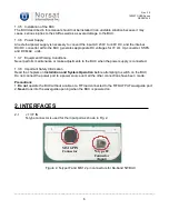
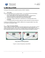
The BUC has body and cover heat sinks with lots of air cooling fins for cooling. Therefore, to achieve
an optimal function of the BUC, it should be mounted upside down so that fins of the body heat sink
are open to fresh air as shown in Fig. 7. Ensure that there are no objects that obstruct a flow of fresh
air into the fins of the body heat sink.
Figure 7. Mounting position of Ka band 5W BUC
4.3
CABLE INSTALLATION
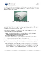
The connections of 7005STC-O3B-A or 7005STC-O3B-B must be done through a waveguide or
coaxial cables. The length of them must be adjusted depending on the installation. An inappropriate
choice of the interface waveguide or cable may result in either a reduction of output power at the
external unit or an excessive distortion of the signal.
Some guidelines to install the interface cables between the internal units (Power supply and
Modem) and the external unit (BUC) are as follows:
a)
Make a plan with the minimal route to be followed by the cables. It is recommended
that 2m of additional cable is added for ease of maintenance.
b)
Secure the cables at each end of the connection.
c)
Ensure that the external connectors are waterproof as well as resistant to other agents.
4.4
WATERTIGHT SEALING UP OF CABLES AND CONNECTORS
The application of moisture-resistant tape over all the connectors is always recommended in every
type of outdoor installations because this ensures an appropriate waterproofing. The application
procedure of this tape is the following:
a) The application of moisture-resistant tape over the connectors is always recommended in
outdoor installations to ensure appropriate waterproofing. The application procedure of this
tape is the following: Ensure that all the connectors are correctly tightened. Cut a piece of
moisture-resistant tape with the desired size and remove the protector plastic of the tape.