,167$//$7,21 &200,66,21,1*+$1'%22.
•
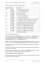
If not, adjust the
Carrier Power
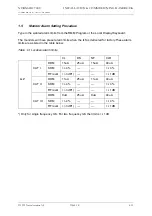
potentiometer on TX1 until the parameter shows 2.00W
•
Repeat for 1W and 0.5W
•
Repeat for TX2.
2.4.2
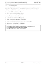
Battery protection cut-off voltage
The purpose of this circuit is to avoid deep discharge and thereby reduced life time of the
backup battery. For normal lead acid accumulators 22V (1.83V/cell) is a reasonable cut-off
voltage.
•
Turn
Off
the
Mains
switch
•
Connect a DC supply, preadjusted to the desired cut-off (
reference
)
voltage
and deacti-
vated, to the external charger input on CI 1376. This is called the
reference supply
.
•
Connect a multimeter in DC volt position to the battery input.
•
Turn the
reference supply
On.
•
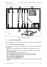
If you measure 0V on the battery adjust the potentiometer on PB1378 until the relay tog-
gles and you measure the
reference voltage
.
•
If you measure the
reference voltage
, adjust the potentiometer until the relay disconnects
and you measure 0V.
2.4.3
Battery charger voltage
The cells of a lead acid battery has an optimal voltage when they are fully charged. This volt-
age is greatly dependent on the temperature. The battery life time will decrease if this rule is
not followed. To meet the demand, the internal battery charger(s) in NM 7050, the PS 1375,
has a temperature compensated charging voltage.
Due to current limiting in PS 1375, a discharged battery will firstly be charged with a constant
current,
≈
2A with one PS1375 and
≈
6A with two PS1375. When the battery draws less than
the current limit, the battery will be charged with a constant voltage (U
BATT
). The factory set-
ting for the internal battery charger is:
UBATT20=27.6V@20°C with
This is the normal final voltage for lead acid accumulators. If your batteries require a different
final voltage, the adjustment procedure is as follows:
•
Turn the
Battery
switch
Off
and have one TX on .
•
Measure the environment temperature T
ENV
(in
°
C)
•
Compute the temperature deviation
∆
T = T
ENV
- 20
°
C
•
Compute the new expected final voltage at your environment temperature as
•
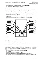
Adjust the potentiometer on PS1375 until you measure U
BATT
on the 27V test point on CI
1376.
⇒
Inner Marker uses an external 10 dB attenuator, use 0.2W, 0.1W and 50mW to cali-
brate.
Carrier Power
is measured prior to the attenuator, but the software will automati-
cally compensate for the 10dB.
k
∆
U
BATT
∆
T
--------------------
40
mV
°
C
--------
–
=
=
U
U
k
T
BATT
BATT
=
+ ⋅
20
∆
Example:
Your battery requires a final voltage of 26V at 20
°
C, and you have measured an environ-
mental temperature of 25
°
C. You should then adjust the charger to give
U
BATT
= 26 + (-0.04)(25 - 20) = 25.8V
Содержание NM 7000 Series
Страница 7: ...1250 5 167580 17 1 1 6 67 0 167 7 21 200 66 21 1 1 22 1DYLD YLDWLRQ 6 ...
Страница 11: ...1250 5 167580 17 1 1 6 67 0 167 7 21 200 66 21 1 1 22 1DYLD YLDWLRQ 6 Figure 2 3 ...
Страница 13: ...1250 5 167580 17 1 1 6 67 0 167 7 21 200 66 21 1 1 22 1DYLD YLDWLRQ 6 ...
Страница 19: ...1250 5 167580 17 1 1 6 67 0 167 7 21 200 66 21 1 1 22 1DYLD YLDWLRQ 6 ...
Страница 21: ...1250 5 167580 17 1 1 6 67 0 167 7 21 200 66 21 1 1 22 1DYLD YLDWLRQ 6 ...
Страница 23: ...1250 5 167580 17 1 1 6 67 0 167 7 21 200 66 21 1 1 22 1DYLD YLDWLRQ 6 ...
Страница 25: ...1250 5 167580 17 1 1 6 67 0 167 7 21 200 66 21 1 1 22 1DYLD YLDWLRQ 6 ...
Страница 27: ...1250 5 167580 17 1 1 6 67 0 167 7 21 200 66 21 1 1 22 1DYLD YLDWLRQ 6 ...
Страница 31: ...1250 5 167580 17 1 1 6 67 0 167 7 21 200 66 21 1 1 22 1DYLD YLDWLRQ 6 ...
Страница 45: ...1250 5 167580 17 1 1 6 67 0 167 7 21 200 66 21 1 1 22 1DYLD YLDWLRQ 6 ...
Страница 55: ...1250 5 167580 17 1 1 6 67 0 167 7 21 200 66 21 1 1 22 1DYLD YLDWLRQ 6 ...
Страница 65: ... ...
Страница 81: ... ...
Страница 111: ... ...
Страница 129: ... ...
Страница 132: ... ...
Страница 134: ...1250 5 167580 17 1 1 6 67 0 167 7 21 200 66 21 1 1 22 1DYLD YLDWLRQ 6 ...
Страница 150: ...1250 5 167580 17 1 1 6 67 0 167 7 21 200 66 21 1 1 22 1DYLD YLDWLRQ 6 ...
Страница 158: ...1250 5 167580 17 1 1 6 67 0 167 7 21 200 66 21 1 1 22 1DYLD YLDWLRQ 6 ...

