

8
4. Place the horizontal drain pan on the opposite side of
the coil. On units with 2 sets of knockouts, remove the
other set of knockouts in the coil spacing plates and
insert support rod.
5. Slide the coil and the horizontal drain pan assembly
back into the unit. Re-attach the tube close off plate.
note: For A-size cabinet applications, it may be
preferrable to remove the blower assembly prior
to installing the coil & drainpan. In this case follow
instructions 1-4 as listed above but also remove the
blower access door and blower assembly. The blower
assembly is secured with two screws on either side
near the front. With these removed the blower assembly
can slide out of the front of the unit. Install the coil and
drain pan as described in step 5 and then replace the
blower assembly. Take care to ensure that the flanges
on the sides of the blower assembly are captured by
the pockets in the blower deck. It may be necessary
to lift the blower assembly during insertion to allow the
lower blower leg to clear the side of the drain pan. The
blower will stop against the back of the blower deck.
Replace the two screws and the blower access door
and procede with steps 6-9.
6. Remove the plug from one of the threaded holes
in the horizontal drain pan. Completely remove the
webbing located in the threaded holes of the drain
pan. iMPortant: If the webbing is not removed, the
condensate will not drain properly and ceiling damage
may occur.
7. Insert the plug (from horizontal drain pan) into the open
and unused drain hole in the drain pan at the bottom
of the unit to block bypass air.
8. Remove the corresponding drain line knockout from
the coil access door to allow access to the horizontal
drain.
9. Replace the door and attach the drain line.
Horizontal installation
MB7 air handlers are shipped from the factory ready
for horizontal left applications and horizontal right
applications. The blowers can be installed horizontally
in an attic, basement, crawl space or alcove. They can
also be suspended from a ceiling in a basement or utility
room in either a right to left airflow or left to right airflow.
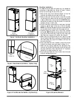
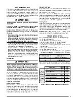
A typical installation of the unit in a suspended horizontal
application is shown in Figure 5.
When mating the blower and coil for horizontal left or
right applications, reference the upflow instructions on
page 6. Make sure to account for the coil orientation by
configuring the coil drain pan assembly properly. Multi-
position procedures are also available in the cased coil
Installation Instructions supplied with the unit.
noteS:
• In many applications when joined with a C6 cased
coil, the shorter horizontal drain pan extension which
is included with the MB7 must be used. This is to avoid
any interference with the extension included with the
C6 and the blower.
• The
air handler may or may not be shipped from the
factory with all the parts required for horizontal left
applications and horizontal right applications. If your
unit does not have parts for a horizontal application, a
kit may be available.
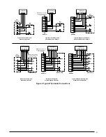
If suspending the air handler from the ceiling, assemble
a support frame (Figure 5) using slotted iron channel and
full threaded rod. Fasten the frame together with nuts,
washers, and lockwashers. Secure the support frame
to the rafters with lag bolts. The air handler can also be
suspended using steel straps around each end of the
unit. The straps should be attached to the air handler with
sheet metal screws and to the rafters with bolts.
Horizontal Left Installations
1. Remove the coil access door.
2. Remove the plug from one of the threaded holes in the
horizontal drain pan. Completely remove the webbing
in the threaded holes of the horizontal drain pan. if the
webbing is not removed, the condensate will not
drain properly and ceiling damage may occur.
3. Insert the plug (from horizontal drain pan) into the open
and unused drain hole in the drain pan at the bottom
of the unit to block bypass air.
4. Remove the corresponding drain line knockout from
the coil access door to allow access to the horizontal
drain.
5. Replace the door and attach the drain line.
Horizontal Right Installations
1. Remove the coil access door. Unscrew the line-set tube
close-off plate from the front left cabinet rail.
2. Slide the coil and drain pan assembly out of the unit.
3. Remove the sheet metal hairpin covers (if supplied)
from the back of the coil and discard.
Figure 5. unit Horizontally Suspended
Threaded
Rod
Lag
Bolt
Nuts (x2)
Washer
and
Lockwasher
Nuts (x2)


