Nordyne MB7BM Series Скачать руководство пользователя страница 5

5

•  It  is  good  practice  to  seal  all  connections  and  joints 

with industrial grade sealing tape or liquid sealant. 
Requirements for sealing ducts vary from region to 
region. Consult with local codes for requirements specific 
to your area.

Supply Air Connections
The supply air must be delivered to the heated space by 
duct(s) secured to the blower’s casing, running full size 
and without interruption. Tape or seal all seams if required 
by local code.

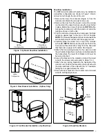
Upflow & Horizontal Applications: To attach the supply air 
duct, bend the flanges (on top of the unit) outward 90° 
with a pair of wide duct pliers. Position the duct on top of 
the blower and secure together with sheet metal screws.

Downflow Applications: Position the blower over the duct 
and secure together with sheet metal screws.

Return Air Connections
The return air must be delivered to the blower by duct(s) 
secured to the casing, running full size and without 
interruption. Tape or seal all seams if required by local code.

Upflow & Horizontal Applications: Position the blower over 
the duct and secure together with sheet metal screws.

Downflow Applications: To attach the supply air duct, 
bend the furnace flanges outward 90° with a pair of wide 
duct pliers. Position the duct on top of the cased coil and 
secure together with sheet metal screws.

Acoustical Duct Work

• 

Certain installations may require the use of acoustical 
lining inside the supply duct work. Acoustical insulation 
must be in accordance with the current revision of the 
Sheet Metal and Air Conditioning Contractors National 
Association (SMACNA) application standard for duct 
liners. Duct lining must be UL classified batts or blankets 
with a fire hazard classification of FHC-25/50 or less.

•  Fiber duct work may be used in place of internal duct 

liners if the fiber duct work is in accordance with the 
current revision of the SMACNA construction standard 
on fibrous glass ducts. Fibrous duct work and internal 
acoustical lining must be NFPA Class 1 air ducts when 
tested per UL Standard 181 for Class 1 ducts.

• 

Damping ducts, flexible vibration isolators, or pleated 
media-style filters on the return air inlet of the air 
handler may be used to reduce the transmission of 
equipment noise eminating from the air handler. These 
treatments can produce a quieter installation, particularly 
in the heated space. However, they can increase the 
pressure drop in the duct system. Care must be taken 
to maintain the proper maximum pressure rise across 
the air handler, temperature rise and flow rate. This 
may mean increasing the duct size and/or reducing the 
blower speed. These treatments must be constructed 
and installed in accordance with NFPA and SMACNA 
construction standards. Consult with local codes for 
special requirements. For best sound performance, be 
sure to install all the needed gaskets and grommets 

Plenums & air ducts

• 

Plenums and air ducts should be installed in 
accordance with the standards of the National Fire 
Protection Association Standard for Installation of 
Air Conditioning Systems (NFPA 90A), Standard for 
Installation of Residence Type Warm Air Heating 
and Air Conditioning Systems (NFPA 90B), and all 
applicable local codes. NFPA publications are available 
by writing to: National Fire Protection Association, 
Batterymarch Park, Quincy, ME 02269 or visit 


www.NFPA.org online.

 WarninG:

all return ducts must be secured to the air 
handler using appropriate methods. all return 
ducts must be adequately sealed. When return 
air is provided through the bottom of the unit, 
the joint between the air handler and the return 
air plenum must be air tight.

return air and circulating air ducts must not be 
connected to any other heat producing device 
such as a fireplace insert, stove, etc. this may 
result in fire, explosion, carbon monoxide 
poisoning, personal injury, or property damage.

•  Design the duct work according to methods described 

by the Air Conditioning Contractors of America (ACCA).

• 

This unit is designed only for use with a return and supply 
duct. The return air duct must have the same free area 
as the opening provided on the air handler. The ducts 
should be appropriately sized to the capacity of the air 
handler to ensure its proper airflow rating.

•  This  unit  should  be  located  with  consideration  of 

minimizing the length of the supply and return ducts. 
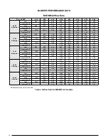
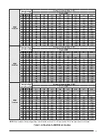
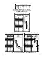
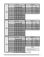
See Tables 4 - 8 (pages 16 - 19) and the rating plate 
for proper circulating airflow data.

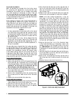
•  Whenever the supply or return air ducts pass through 

the floor, a 1/4” thick noncombustible resilient gasket 
must be used between the duct, unit and floor

•  Use  transition  fittings  if  the  supply  and/or  return  air 

openings of the unit do not match the duct openings. 
These transitions should be dimensioned in accordance 
with standard practice as specified in the ASHRAE 
recommendations for duct transitions.

•  The  supply  air  ductwork  must  be  of  noncombustible 

material for the first 24 inches from the unit. Some 
installations with a short, straight run from the unit to 
the first branch takeoff may require acoustical lining 
inside the supply air ductwork. Consult with local codes 
for requirements specific to your area.

•  Flexible  connectors  may  be  used  between  the  unit 

and the ductwork to prevent transmission of vibration 
from the unit to the structure. If electric heater kits are 
installed, heat resistant material must be used for the 
flexible connector at the supply air end of the unit.

Содержание MB7BM Series

Страница 1: ...nt role as well Pay attention to all safety warnings and any other special notes highlighted in the manual Improper installation of the furnace or failure to follow safety warnings could result in ser...

Страница 2: ...ing 11 Turning the Blower Off 11 Blower Configurations 11 Selecting minimum Electric Heat Airflow 11 Determining Nominal System Capacity 11 3 speed Units 11 High Efficiency Units 12 Selecting Basic He...

Страница 3: ...ment Do not store any of the following on or in contact with the unit Rags brooms vacuum cleaners or other cleaning tools spray or aerosol cans soap powders bleaches waxes cleaning compounds plastics...

Страница 4: ...dbesetintopositionbeforerouting the refrigerant tubing Operation of an Air Handler During Construction CAUTION Failure to follow these instructions will void the factory warranty and may significantly...

Страница 5: ...tments must be constructed and installed in accordance with NFPA and SMACNA construction standards Consult with local codes for special requirements For best sound performance be sure to install all t...

Страница 6: ...nts air handler INSTALLATION The MB7 Series air handler is shipped ready for vertical upflow installation and is approved for attic basement alcove closetorcrawlspaceinstallationwithzeroclearance to c...

Страница 7: ...ne gasket tape to the top of the air handler NOTE The blowers flanged surface is now beneath the air handler and will connect with the supply air duct 4 Carefully place the cased coil on top of the mo...

Страница 8: ...ion of the unit in a suspended horizontal application is shown in Figure 5 When mating the blower and coil for horizontal left or right applications reference the upflow instructions on page 6 Make su...

Страница 9: ...gures 14 16 Use only copper wire for the line voltage power supply to this unit Use proper code agency listed conduit and a conduit connector for connecting the supply wires to the unit Aluminum suppl...

Страница 10: ...erkitforyour unit by referring to the list below or the units rating label A Size Cabinet 15Kw max B Size Cabinet 20Kw max C Size Cabinet 20Kw max 1 Connect the 2 wire plug of the air handler to the m...

Страница 11: ...Disconnect all electrical power to the unit and remove the upper door 2 Remove the black and red wires from the blower motor jumping terminal Discard the blower motor jumping terminal Startup Adjustme...

Страница 12: ...ch nominal system capacity When operating in the heat pump mode a higher basic airflow setting will increase the energy efficiency and capacitybutwillalsodecreasethesupplyairtemperature For maximum ca...

Страница 13: ...eate excessive loads on the motor resulting in higher than normal operating temperatures and shortened service life It is recommended that the blower compartment be cleaned of dirt or lint that may ha...

Страница 14: ...mension B Dimension C A 12 3 4 24 3 4 14 1 4 B 12 3 4 24 3 4 17 1 2 C 18 1 4 27 1 2 21 B A 12 7 8 3 4 TYP 1 3 4 1 7 8 K O 3 1 4 1 1 4 C 22 1 1 7 8 3 1 2 5 1 2 2 5 8 1 1 8 K O TYP 1 1 4 2 7 8 TOP VIEW...

Страница 15: ...ount Kit Blower Motor Blower Wheel Blower Housing Transformer Control Board Coil Assembly Outlet Heater Box Lower Front Bracket Blower Door Motor Control Board Rear Bracket Front Joining Bracket Figur...

Страница 16: ...0 845 780 705 610 530 Corrected ESP1 0 08 0 19 0 31 0 42 0 54 0 65 0 76 Med 1335 1290 1235 1175 1100 1015 925 805 Corrected ESP1 0 10 0 22 0 34 0 46 0 59 0 71 High 1470 1425 1360 1300 1225 1135 1050 9...

Страница 17: ...685 0 1 1 0 1095 1040 995 950 900 850 805 750 1 1 1 0 1155 1105 1060 1010 965 920 870 825 0 0 0 1 1230 1185 1140 1090 1045 1010 965 920 1 0 0 1 1285 1260 1210 1165 1125 1080 1040 1010 0 1 0 1 1330 12...

Страница 18: ...0 1 0 650 0 0 1 1 2 TON 1300 0 0 1 1 4 TON 700 0 1 0 0 1350 0 1 0 0 750 0 1 0 1 1400 0 1 0 1 800 0 1 1 0 2 5 TON 1450 0 1 1 0 850 0 1 1 1 1500 0 1 1 1 875 1 0 0 0 1550 1 0 0 0 950 1 0 0 1 1600 1 0 0 1...

Страница 19: ...0 1 0 0 700 1 15 1300 1 0 1 0 1 750 1 20 1500 1 0 1 1 0 800 1 25 N A 1 0 1 1 1 850 1 30 N A 1 1 0 0 0 875 1 1 0 0 1 950 1 1 0 1 0 1050 1 1 0 1 1 1150 1 1 1 0 0 1250 1 1 1 0 1 1350 1 1 1 1 0 1400 1 1 1...

Страница 20: ...1 7 68 1 50 25 70 020H XX 53 1 103 1 60 110 46 5 43 3 89 8 50 45 90 C 2000CFM None 5 5 15 15 5 5 15 15 005H XX 30 30 35 35 26 7 26 7 30 30 008H XX 44 6 44 6 45 45 39 3 39 3 40 40 010H XX 55 55 60 60 4...

Страница 21: ...Thermostat Y1 C Y1 W2 Typical 2 Stage Air Conditioner with Variable Speed Air Handler Typical 2 Stage Heat Pump with Variable Speed Air Handler Y2 Y2 Y2 Y2 OUT W E R Air Conditioner Air Handler Air C...

Страница 22: ...age Control Board MB7BM Models Figure 11 Two Stage Control Board MB7EM VM Models LED 1 BLWDTC BLWDTC_R HEAT COOL EAC L 1 L 2 P2 R C G W Y 3A Fuse HEATER P1 C R G Y2 Y O 1W 2W 1Y L LED 1 HEATER P1 L 2...

Страница 23: ...W C EXPANSION PORT R RED GREEN TEST PORT BLOWER MOTOR RED INPUTS COOL HEAT FAN SPEED OUTPUTS STATUS LIGHTS 2 3 4 5 6 7 8 OFF ON A B GREEN RED STATUS NOT USED TEST PORT BLOWER MOTOR R C Y1 TWIN DEHUM...

Страница 24: ...PLUG HOUSING WHEN HEATER KIT NOT INSTALLED BLACK RED WHITE BROWN BROWN BLACK WHITE RED GRAY YELLOW WHITE GREEN GRAY RED NOTES 1 The blower motor speed tap connection may not be as shown See the Insta...

Страница 25: ...2 3 4 5 6 9 PIN HOUSING 9 PIN PLUG 6 PIN PLUG HARNESS BLACK WHITE GRAY RED BLACK RED WHITE BLACK MOTOR 6 PIN PLUG HARNESS WHITE BLACK BLUE GREEN YELLOW ORANGE RED BROWN BLUE GREEN ORANGE RED BROWN YE...

Страница 26: ...R BLACK WHITE 6 PIN PLUG 6 PIN PLUG BLACK WHITE BLACK WHITE GRAY RED BLACK HARNESS HARNESS GREEN BROWN RED ORANGE YELLOW GREEN BLUE BROWN RED ORANGE YELLOW GREEN BLUE RED CUT WIRES TO REMOVE PLUG HOU...

Страница 27: ...delay W Y AUX HEAT On 5 KW Stage 1 Heat on instantly Cool blower on after 3 second delay 10 KW Stage 1 Heat on instantly Cool blower on after 3 second delay Stage 2 Heat on after 5 seconds delay 15 KW...

Страница 28: ...ly Blower off after 15 second delay W1 W2 EHEAT On 5 KW Stage 1 Heat on instantly Heat blower on after 3 second delay 10 KW Stage 1 Heat on instantly Heat blower on after 3 second delay Stage 2 Heat o...

Страница 29: ...off instantly Heat blower turns off after 40 second delay W1 W2 Y Y2 AUX HEAT On 5 KW Stage 1 Heat on instantly Cool blower on after 3 second delay 10 KW Stage 1 Heat on instantly Cool blower on afte...

Страница 30: ...30...

Страница 31: ...31...

Страница 32: ...Replaces 7091750 ATTENTION INSTALLERS It is your responsibility to know this product better than your customer This includes being able to install the product according to strict safety guidelines and...

Отзывы: