11
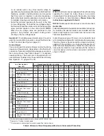
Control
Signal
Operation
Board Action
W1 only
On
Stage 1 Heat on instantly
Heat blower on after 3 second delay
Stage 3 & 5 Heat on after 1 minute delay
Stage 2 Heat on after 2 minute delay
Stage 4 & 6 Heat on after 3 minute delay
Off
Heat stages off instantly
Blower off after 15 second delay
W1 & W2
On
Stage 1 Heat on instantly
Heat blower on after 3 second delay
Stage 3 & 5 Heat on after 10 second delay
Stage 2 Heat on after 20 second delay
Stage 4 & 6 Heat on after 30 second delay
Off
Heat stages off instantly
Blower off after 15 second delay
W1 & Y/Y2
On
Stage 1 Heat on instantly
Cool blower on after 3 second delay
Stage 3 & 5 Heat on after 1 minute delay
Stage 2 Heat on after 2 minute delay
Stage 4 & 6 Heat on after 3 minute delay
Off
Heat stages & Cool blower off instantly
Heat blower energizes and then turns off after 15
second delay
W1, W2 &
Y/Y2
On
Stage 1 Heat on instantly
Cool blower on after 3 second delay
Stage 3 & 5 Heat on after 10 second delay
Stage 2 Heat on after 20 second delay
Stage 4 & 6 Heat on after 30 second delay
Off
Heat stages and Cool blower off instantly
Heat blower energizes and then turns off after 15
second delay
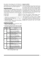
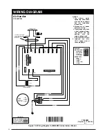
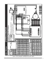
Table 3. Heating Element Logic
When electric heat packages with circuit breakers are
fi eld-installed, the circuit breaker may be used as a
disconnecting means in most applications. Reference the
NEC and local codes for disconnect requirements.
If a heater kit is installed:
The MB6 indoor blower is shipped from the factory without
an electric heater kit installed. If Electric heat is desired,
the H6HK heater kit may be purchased separately and
fi eld installed. Determine the correct size heater kit for your
unit by referring to the list below or the units rating label.
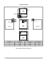
A Size Cabinet ............................................... 15Kw max
B Size Cabinet ............................................... 20Kw max
C Size Cabinet ............................................... 20Kw max
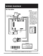
1. Connect the 2 wire plug of the indoor blower to the
mating 2 wire plug of the heater kit.
2. Connect the line voltage leads to the circuit breaker or
terminal block provided.
3. Connect the heater kit plug with the mating receptacle
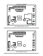
on the indoor blower control board.
If a heater kit is not installed:
1. Remove the 2 wire plug of the indoor blower by cutting
the wires and discarding the plug.
2. Strip the ends of the 2 indoor blower wires and connect
to the line-voltage leads with the 2 wire nuts provided.
Optional Humidistat
(MB6VM Models Only)
The optional humidistat may be installed in the return air
duct to provide excellent humidity control when needed
and maximum system capacity and energy effi ciency
when humidity levels are normal. The humidistat senses
when humidity in the return air stream is above a preset
level (fi eld adjustable) and sends a signal to the motor to
reduce the airfl ow so that more moisture may be removed
until the humidity level drops. The indoor blower is pre-
programmed for humidistat operation.
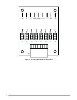
Remove jumper connector installed between the two
terminals marked
HUM
on the variable speed board.
Install the humidistat in the return air duct as directed
in the installation instructions included with the kit. Wire
the humidistat through the low-voltage wire entrance in
the indoor blower to the control board terminal marked
DEHUM
. Wire the humidistat to open on rise in humidity.


