10
on an outside wall or any other location where its
operation may be adversely affected by radiant heat from
fi replaces, sunlight, or lighting fi xtures, and convective
heat from warm air registers or electrical appliances.
Refer to the thermostat manufacturer’s instruction sheet
for detailed mounting and installation information.
• Install the grommet (packed with the unit) in the hole
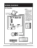
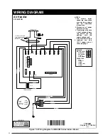
for low-voltage wires. Connect the low-voltage wiring to
the thermostat and the outdoor unit and the appropriate
screw terminal located on the control board.
NOTE:
When the low voltage wires are positioned in this
grommet, the grommet will prevent chafi ng and/or
shorting of the low voltage leads.
Important!
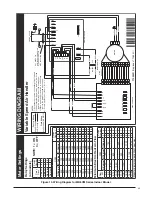
On variable speed models when the unit is
used in an air conditioning system, connect the
O
terminal
to the
Y
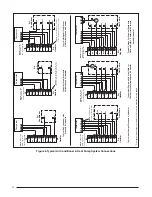
terminal. See Figure 6 (page 12)
.
Control Board
The control board in the indoor blower controls the timing
sequence of the elements. Depending on the thermostat
connection, there are multiple timing sequence variations
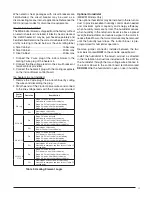
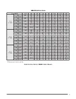
that can be chosen. See Table 3 (page 11) for element
sequence timing. The board also is equipped with a 3
second blower on delay and a 15 second blower off delay.
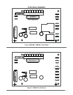
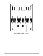
See Figures 9 - 11 (pages 21 & 22).
Twinning
MB6 indoor blowers are not supplied with a built in twinning
capability. To connect two indoor blowers to a common
single stage AC condensing unit or heat pump, a twinning
kit is available for fi eld installation.
Please follow the
instructions supplied with the kit.
NOTE:
Variable speed indoor blowers cannot be twinned.
Heater Kits
Field-installed electric heater kits are available. Instructions
for installing the electric heaters are included with the
heaters. See heater kit information can be found in the
Technical Specifi cations.
Indoor blowers set up with 15 kw or more of electric heat
will normally be confi gured for multiple-circuit power supply.
They may, however, be connected to a single-circuit power
supply with the addition of a single circuit accessory kit
(See Technical Specifi cations). Select the wire size and
over-current protection in accordance with the minimum
circuit ampacity and maximum over-current protection
shown in Table 2.
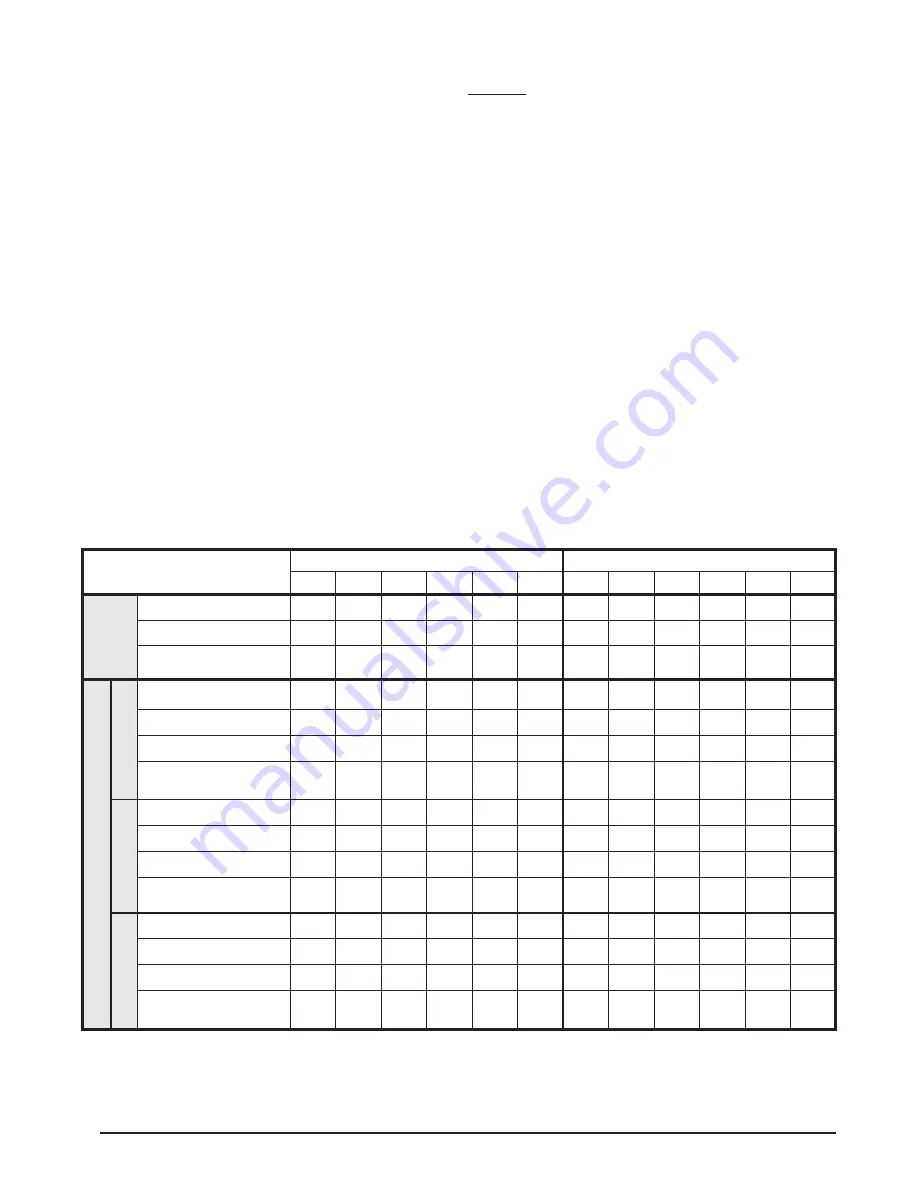
Table 2. Minimum Circuit Ampacity & Maximum Overcurrent Protection
Aux. Heat Installed
(Nom. KW)
Single Phase, 240 VAC, 50 & 60Hz
Single Phase, 208 VAC, 60Hz
NONE
005H
008H
010H
015H
020H
NONE
005H
008H
010H
015H
020H
Single Cir
cuit
***Min. Circuit Amp.
7.5
32.5
46.6
57.5
82.5
107.5
7.5
29.1
41.2
50.8
72.4
94.0
*Wire AWG 75
o
C
14
8
8(6**)
6
4(3**)
2
14
10(8**)
8
6
4
3
Maximum Over-current
Rating
15
40
50
60
90
125
15
30
50
60
80
100
Multiple Cir
cuit
Cir
cuit A
***Min. Circuit Amp.
7.5
32.5
46.6
57.5
57.5
57.5
7.5
29.1
41.2
50.8
50.8
50.8
*Wire AWG 60
o
C
14
8
6
4
4
4
14
10(8**)
6
6
6
6
*Wire AWG 75
o
C
14
8
8(6**)
6
6
6
14
10(8**)
8
6
6
6
Maximum Over-current
Rating
15
40
50
60
60
60
15
30
50
60
60
60
Cir
cuit B
***Min. Circuit Amp.
-
-
-
-
25.0
50.0
-
-
-
-
21.6
43.3
*Wire AWG 60
o
C
-
-
-
-
10
6
-
-
-
-
10
6
*Wire AWG 75
o
C
-
-
-
-
10
8
-
-
-
-
10
8
Maximum Over-current
Rating
-
-
-
-
30
60
-
-
-
-
25
50
Cir
cuit C
***Min. Circuit Amp.
-
-
-
-
-
-
-
-
-
-
-
-
*Wire AWG 60
o
C
-
-
-
-
-
-
-
-
-
-
-
-
*Wire AWG 75
o
C
-
-
-
-
-
-
-
-
-
-
-
-
Maximum Over-current
Rating
-
-
-
-
-
-
-
-
-
-
-
-
*All wire sizes for copper conductors only, based on NEC Table 310-16.
**Required for C-cabinet variable speed.
***Circuit ampacity slightly higher for variable speed. See label on blower.


