6
Unplugging the Nozzle
1. Close the air shut-off valve (21).
2. Set the air pressure regulator (20) to 0 bar/psi.
Pull on the relief valve (19) lanyard to relive
system air pressure.
3. Set the RUN/OFF/TEST switch (6) to OFF.
4. Remove the nozzle (11) and clean with flushing
thinner and a nozzle brush.
5. Loosen the locknut (13). Back out the armature
sleeve (12) one turn.
6. Install the nozzle (11).
7. Close the relief valve (19).
8. Open the air shut-off valve (21). Set the air
pressure regulator (20) to 0.2 bar (3 psi).
9. Open the bleeder valve (15) to bleed air out of the
hose. Close the bleeder valve.
10. Set the air pressure regulator (20) to
0.4-0.7 bar (5-10 psi).
11. Set the RUN/OFF/TEST switch (6) to ON.
12. Adjust the dot size. Refer to Adjusting the Dot
Size.
Maintenance
Table 2 provides maintenance procedures for the
Ink-Dot system.
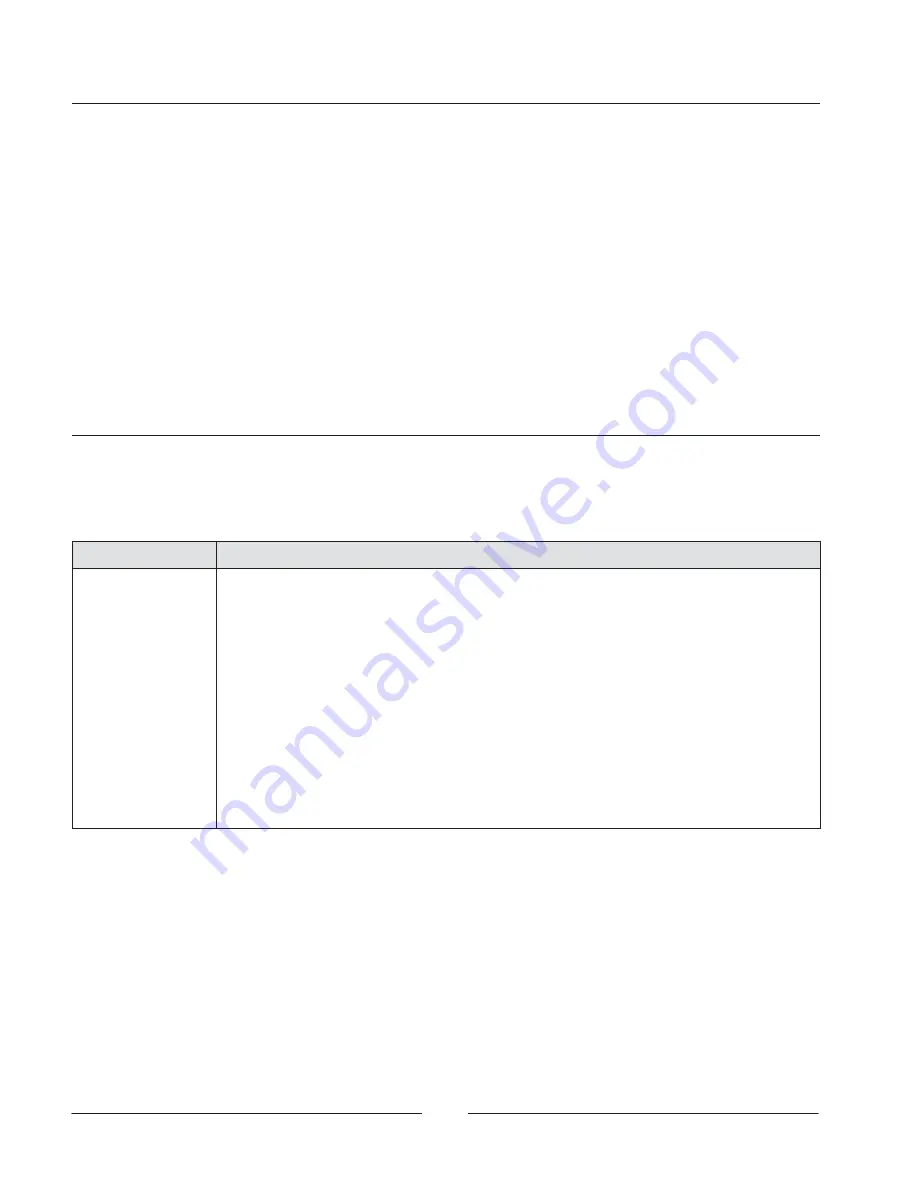
Table 2 Maintenance Schedule
Frequency
Task
Daily
Wipe or brush the nozzle once per shift with a solvent that is compatible with the ink.
A nozzle brush is included with the gun.
Weekly
1. Refer to the Ink-Dot gun manual to check the Ink-Dot gun mounting angle.
2. Check the distance between the
S
proximity sensor and can conveyor
S
Ink-Dot gun and can conveyor
S
gun nozzle and proximity sensor
3. Make sure that the proximity sensor is perpendicular to the side of the can.
Periodically
Check the ink level in the reservoir.
3–6 months
Flush the system with a compatible solvent and replace the inline filter element.
9–12 months
Replace the ball and seat, seals, O-rings and inline filter element in the gun.
Содержание Ink-Dot System
Страница 8: ...8...


