Instruction Sheet
Part 108864A
E
2003 Nordson Corporation
P/N 108864A
Driver Module Adjustment
Ink-Dot
t
Series I
Adjusting Dot Size
WARNING: Allow only qualified personnel
to perform the following tasks. Follow the
safety instructions in this document and all
other related documentation.
WARNING: Disconnect equipment from
line voltage. Failure to observe this
warning may result in personnel injury,
death, or equipment damage.
1. See Figure 1. Remove the screws (1) and
washers (2) securing the driver module (3) to
the enclosure (4).
NOTE: The driver module has two channels. Each
channel controls one spray gun. The channel
potentiometers are located on the back side of the
driver module.
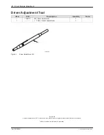
2. Turn the desired channel potentiometer (5, 6)
using the trimmer adjustment tool provided with
this kit.
To Increase Dot Size: Turn the potentiometer
clockwise.
To Decrease Dot Size: Turn the potentiometer
counterclockwise.
3. Use the screws and washers to install the driver
module to the enclosure. Tighten the screws
securely.
1200147A
12
11
10
9
8
7
6
5
13
14
15
16
17
18
19
20
21
22
23
24
MODEL
PART NO.
SERIAL NO.
NORDSON
CORPORATION
AMHERST
OHIO
5
4
6
1
2
3
Figure 1
Driver Module Adjustment
1. Screws
2. Washers
3. Driver module
4. Enclosure
5. Channel 1
potentiometer
6. Channel 2
potentiometer


