background image

98

105

13

14

99

14

107

1

1

1

101

14

1

104

14

102

100

14

14

14

103

106

14

14

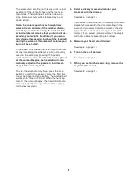
14

14

14

14

1

107

17

17

93

117

108

35

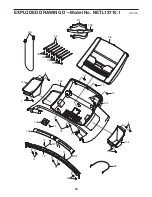
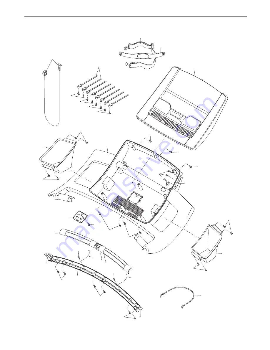
EXPLODED DRAWING D—Model No. NETL12710.1

R1010A

Содержание NETL12710.1

Страница 1: ...is manual for future reference QUESTIONS If you have questions or if there are missing parts please contact us UK Call 08457 089 009 From Ireland 053 92 36102 Website www iconsupport eu E mail csuk ic...

Страница 2: ...ST 30 EXPLODED DRAWING 32 ORDERING REPLACEMENT PARTS Back Cover RECYCLING INFORMATION Back Cover This drawing shows the locations of the warning decals If a decal is missing or illegible call the tele...

Страница 3: ...uit When replacing the fuse in the power cord adapter insert an ASTA approved BS1362 13 amp fuse into the fuse carrier 12 If an extension cord is needed use only a 3 conductor 14 gauge 1 mm2 cord that...

Страница 4: ...rly 24 DANGER Always unplug the power cord immediately after use before cleaning the treadmill and before performing the mainte nance and adjustment procedures described in this manual Never remove th...

Страница 5: ...ng the treadmill If you have questions after read ing this manual please see the front cover of this man ual To help us assist you please note the product model number and serial number before contact...

Страница 6: ...assembled To avoid dam aging parts do not use power tools for assembly Extra hardware may be included Base Foot Spacer 36 2 3 8 Star Washer 11 6 8 x 1 2 Screw 1 14 8 x 1 Tek Screw 2 4 3 8 Nut 10 4 1 4...

Страница 7: ...94 in the locations shown with two 8 x 1 Tek Screws 2 Then attach the other two Base Feet 92 with two 8 x 1 Tek Screws 2 See the inset drawing Cut the plastic tie near the Upright Wire 85 1 94 2 92 9...

Страница 8: ...e heads of the Patch Bolts touch the Right Upright do not fully tighten the Patch Bolts yet Then partially tighten the 3 8 x 2 1 4 Patch Bolt 31 83 3 Identify the Right Upright 83 which is marked with...

Страница 9: ...so that the treadmill is more stable do not fully fold the Frame yet Insert a 3 8 x 5 1 2 Patch Bolt 7 a 3 8 x 3 3 4 Patch Bolt 97 and a 3 8 x 2 1 4 Patch Bolt 31 with three 3 8 Star Washers 11 into...

Страница 10: ...Route the console wire through the large holes in the top and bottom of the Right Handrail Set the Right Handrail 79 on the Console Frame 81 Start a 1 4 x 1 2 Patch Bolt 8 with a 1 4 Star Washer 12 i...

Страница 11: ...U TURN ON THE POWER Then remove the wire tie from the Upright Wire Console Assembly 9 Console Wire Wire Tie 85 79 83 85 Console Wire 10 Slide a Handrail Cover 77 onto the lower end of each Handrail 78...

Страница 12: ...essory Tray 104 to the console as sembly with eight 8 x 1 2 Screws 1 104 1 1 101 1 1 12 Console Assembly 11 Start two 1 4 x 1 2 Patch Bolts 8 into the lower end of each Handrail 78 79 Tighten all sixt...

Страница 13: ...the latch knob are oriented as shown Attach the upper end of the Storage Latch 51 to the Frame Crossbar 109 with a 3 8 x 2 Bolt 3 and a 3 8 Nut 10 Attach the Storage Latch 51 to the Base 94 with a 3 8...

Страница 14: ...on such as saliva or contact lens so lution wet both electrode areas Return the sensor unit to a position against your chest CARE AND MAINTENANCE Thoroughly dry the chest pulse sensor after each use T...

Страница 15: ...If heart rate readings do not appear until you begin perspiring rewet the electrode areas As you walk or run on the treadmill position your self near the center of the walking belt For the console to...

Страница 16: ...eadmill 2 If you are plugging in the power cord in Australia go to step 3 If you are plugging in the power cord in the UK first press the pins on the power cord into the metal clips in the adapter as...

Страница 17: ...e with your wireless network through an optional iFit Live module With the iFit Live mode you can download personalized work outs create your own workouts track your workout re sults and access many o...

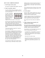
Страница 18: ...the clip Note The console can display speed and distance in either kilometers or miles To find which unit of mea surement is selected see THE INFORMATION MODE on page 24 For simplicity all instructio...

Страница 19: ...nsor and the chest pulse sensor at the same time the console will not display your heart rate accu rately For information about the chest pulse sen sor see page 14 Before using the handgrip pulse sens...

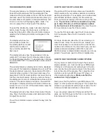
Страница 20: ...erformance workout you can change the intensity of your workout Press the Select button Then press the increase or decrease button on the screen to change the intensity 3 Start the workout Press the S...

Страница 21: ...l will auto matically adjust to the speed and incline set tings for the next segment To stop the workout at any time press the Stop button To restart the workout press the Start but ton or the Speed i...

Страница 22: ...is in tier three Press the Select button If you choose to compete against a group press the Race Against a Pack button Select a level of difficulty for the race by pressing the increase and decrease...

Страница 23: ...cline settings of the race The profile will appear in the lower part of the screen The rate at which your opponents recover their energy rec The bank or amount of energy your opponents have left As th...

Страница 24: ...and decrease buttons to adjust the contrast To exit the information mode remove the key from the console HOW TO USE THE IFIT LIVE MODE The optional iFit Live module allows your treadmill to communica...

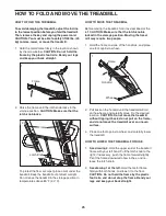
Страница 25: ...latch knob is locked in the storage position Moving the tread mill may require two people 1 Hold the frame and one of the handrails and place one foot against a wheel 2 Pull back on the handrail unti...

Страница 26: ...s and then press the switch back in b Make sure that the power cord is plugged in If the power cord is plugged in unplug it wait for five minutes and then plug it back in c Remove the key from the con...

Страница 27: ...d then return to the minimum level This will recalibrate the incline system If the incline does not calibrate press the Stop button and then press the Incline increase or decrease button again When th...

Страница 28: ...the walking belt is centered b If the walking belt slips when walked on first re move the key and UNPLUG THE POWER CORD Using the hex key turn both idler roller bolts clock wise 1 4 of a turn When the...

Страница 29: ...our goal is to strengthen your cardiovascular system you must perform aerobic exer cise which is activity that requires large amounts of oxygen for prolonged periods of time For aerobic ex ercise adju...

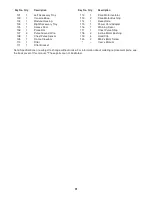
Страница 30: ...Walking Platform 39 2 Belt Guide 40 1 Left Foot Rail Cover 41 1 Right Foot Rail Cover 42 1 Drive Roller Pulley 43 1 Magnet 44 1 Reed Switch 45 1 Reed Switch Clamp 46 1 Drive Motor Belt 47 1 Drive Mot...

Страница 31: ...Crossbar 110 1 Filter 111 1 Filter Bracket 112 1 Drive Motor Isolator 113 2 Drive Motor Bushing 114 1 Receptacle 115 1 Power Cord Adapter 116 1 Warning Decal 117 1 Chest Pulse Strap 118 2 Incline Mot...

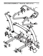
Страница 32: ...47 38 116 40 24 42 50 56 60 59 51 6 3 10 26 28 28 37 37 28 28 28 41 21 21 20 45 44 43 30 30 17 17 54 53 14 57 46 17 32 33 55 48 111 17 120 110 10 109 91 91 112 113 18 18 18 18 18 18 18 18 14 58 1 32...

Страница 33: ...76 75 74 68 14 14 14 68 70 61 49 49 119 49 118 66 69 29 29 65 22 22 63 63 16 16 64 64 10 10 62 52 49 52 49 49 49 114 115 71 73 119 119 EXPLODED DRAWING B Model No NETL12710 1 R1010A 33...

Страница 34: ...10 87 86 95 95 96 92 2 2 1 1 1 84 79 81 78 82 85 9 5 9 5 4 4 8 12 4 9 34 80 80 34 11 7 72 17 107 36 36 1 77 77 4 9 8 12 8 8 27 27 11 31 1 88 90 1 92 2 10 94 67 96 96 96 10 67 9 9 31 97 17 34 EXPLODED...

Страница 35: ...98 105 13 14 99 14 107 1 1 1 101 14 1 104 14 102 100 14 14 14 103 106 14 14 14 14 14 14 1 107 17 17 93 117 108 35 EXPLODED DRAWING D Model No NETL12710 1 R1010A...

Страница 36: ...part s see the PART LIST and the EXPLODED DRAWING near the end of this manual RECYCLING INFORMATION This electronic product must not be disposed of in municipal waste To pre serve the environment this...

Отзывы: