background image

5

ASSEMBLY

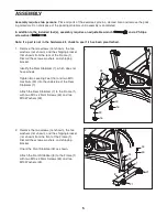
Assembly requires two persons.

Place all parts of the exercise cycle in a cleared area and remove the pack-

ing materials. Do not dispose of the packing materials until assembly is completed.

In addition to the included tool(s), assembly requires an adjustable wrench

and a Phillips

screwdriver

.

Note: If a part is not in the hardware kit, check to see if it has been preattached.

1. Remove the two screws (not shown), the two

washers (not shown), and the shipping bracket

(not shown) from the rear of the Frame (1).

Discard the screws, washers, and shipping

bracket.

Identify the Rear Stabilizer (7), which does not

have wheels.

Tighten two Leveling Feet (16) and two M10

Hex Nuts (49) into the underside of the Rear

Stabilizer (7).

Attach the Rear Stabilizer (7) to the Frame (1)

with two M10 x 25mm Screws (34) and two

M10 Washers (33).

2. Remove the two screws (not shown), the two

washers (not shown), and the shipping bracket

(not shown) from the front of the Frame (1).

Discard the screws, washers, and shipping

bracket.

Orient the Front Stabilizer (8) as shown.

Attach the Front Stabilizer (8) to the Frame (1)

with two M10 x 25mm Screws (34) and two

M10 Washers (33).

1

34

33

49

49

16

7

1

1

8

16

34

33

21

21

34

33

2

Содержание GX2 Sport NTEX03009.3

Страница 1: ...nce Model No NTEX03009 3 Serial No Write the serial number in the space above for reference www iconeurope com QUESTIONS If you have questions or if there are missing parts please contact us Call 0845...

Страница 2: ...ORDERING REPLACEMENT PARTS Back Cover NordicTrack is a registered trademark of ICON IP Inc WARNING DECAL PLACEMENT This drawing shows the location s of the warning decal s If a decal is missing or ill...

Страница 3: ...rcise cycle on a level surface with a mat beneath it to protect the floor or carpet Make sure that there is at least 2 ft 0 6 m of clearance around the exercise cycle 6 Inspect and properly tighten al...

Страница 4: ...e the exercise cycle If you have questions after reading this manual please see the front cover of this manual To help us assist you note the product model number and serial number before contacting u...

Страница 5: ...the rear of the Frame 1 Discard the screws washers and shipping bracket Identify the Rear Stabilizer 7 which does not have wheels Tighten two Leveling Feet 16 and two M10 Hex Nuts 49 into the undersid...

Страница 6: ...en the Adjustment Knob Move the Handlebar Post 4 upward or downward slightly to make sure that the Adjustment Knob 23 is firmly engaged in an adjustment hole in the Handlebar Post 3 4 3 Identify the R...

Страница 7: ...stment Knob pull it outward and insert the Seat Post 2 into the Frame Next move the Seat Post 2 upward or down ward to the desired position release the Adjustment Knob 23 into an adjustment hole in th...

Страница 8: ...downward and insert the Seat Carriage 3 into the Seat Post Slide the Seat Carriage 3 to the desired posi tion release the Adjustment Knob 23 into an adjustment hole in the Seat Carriage and then tight...

Страница 9: ...ease the adjustment knob into an adjustment hole in the handlebar post and tighten the adjustment knob Make sure that the adjustment knob is engaged in an adjustment hole HOW TO ADJUST THE PEDAL STRAP...

Страница 10: ...e 38 2 Flywheel Bracket 39 1 Sleeve 40 2 M8 Locknut 41 2 Brake Pad 42 1 Brake Clamp 43 1 Small Knob Washer 44 2 Flywheel Bearing 45 2 Crank Bearing 46 4 Wheel Bearing 47 1 Flywheel Sprocket 48 2 Snap...

Страница 11: ...3 10 9 50 42 62 23 60 52 63 58 17 23 12 53 32 61 61 56 24 25 64 51 41 65 34 33 34 33 1 18 50 50 46 21 46 49 16 46 50 21 46 50 49 16 18 8 49 16 18 7 6 29 40 38 55 39 44 44 36 31 47 28 57 37 55 38 40 29...

Страница 12: ...lp us assist you be prepared to provide the following information when contacting us the model number and serial number of the product see the front cover of this manual the name of the product see th...

Отзывы: