


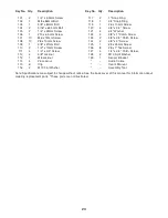

10
14
86
20
21
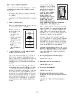
9. Identify the Right Upper and Lower Covers (14,
15), which are marked with “Right” stickers, and
orient them as shown.
Attach the Right Upper and Lower Covers (14,
15) around the Right Handlebar (20) with two
#8 x 3/4" Screws (86).
Repeat this step for the Left Handlebar (21).
9
15
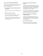
10. Identify a set of Right and Left Link Covers (22,
23), which are marked with “Right” and “Left”
stickers, and orient them as shown.
Attach the Right and Left Link Covers (22, 23)
around the Right Handlebar (20) with four #8 x
1" Tek Screws (126).
Repeat this step for the other side of the
elliptical strider.
10
20
126
126
23
22
11. Plug the AC power adapter into the jack on the front of the elliptical strider (see HOW TO PLUG IN THE AC
POWER ADAPTER on page 12).
IMPORTANT: If the elliptical strider has been exposed to cold temper-
atures, allow it to warm to room temperature before plugging in the AC power adapter. If you do not
do this, you may damage the console displays or other electronic components.
Make sure that all parts are properly tightened before you use the elliptical strider.
Note: After assembly
is completed, some extra parts may be left over. Place a mat beneath the elliptical strider to protect the floor.