


12
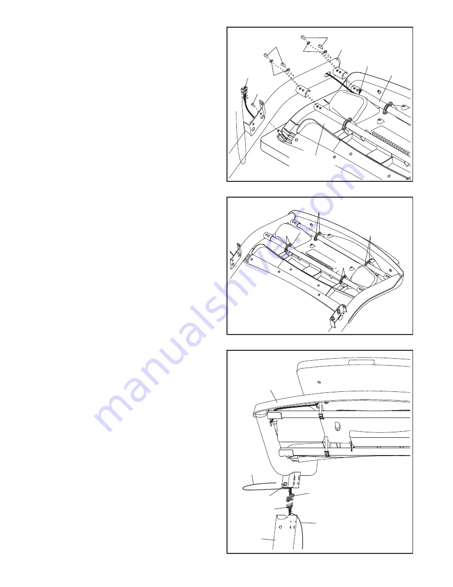
12. Position the console wire under the indicated
Handrail Crossbar (74) as you set the Right
Handrail (77) on the console assembly.
Be
careful not to pinch the console wire.
Attach the Right Handrail (77) to the console as-
sembly with a #8 x 3/4" Screw (1), four 1/4" x
3/4" Screws (3), and four 1/4" Star Washers
(11);
Tighten the #8 x 3/4" Screw, but do not
tighten the 1/4" x 3/4" Screws yet.
Attach the Left Handrail (not shown) in the same
way. Note: There is not a wire on the left side.
12
1
77
3
11
Console
Wire
74
3
11
Console
Wire
13. Tighten the eight #8 x 3/4" Screws (1).
Be care-
ful not to overtighten the Screws.
13
1
1
1
1
14. Remove the plastic ties from the 5/16" Cage
Nuts (34) (only one side is shown). If necessary,
press the Cage Nuts back into place.
With the help of a second person, hold the con-
sole assembly near the Right Upright (82) and
the Left Upright (not shown).
Connect the Upright Wire (85) to the console
wire.
See the inset drawing in step 8. The
connectors should slide together easily and
snap into place.
If they do not, turn one con-
nector and try again.
IF YOU DO NOT CON-
NECT THE CONNECTORS PROPERLY, THE
CONSOLE MAY BECOME DAMAGED WHEN
YOU TURN ON THE POWER.
Then, remove
the wire ties from the wires.
Console
Assembly
14
Console
Wire
Wire
Tie
Wire
Tie
82
34
85
Console
Assembly