


Nokia Custome Care
Service Sofftware and Tuning Instructions
RH-37
Issue 1 07/04
Nokia Corporation
Page 45
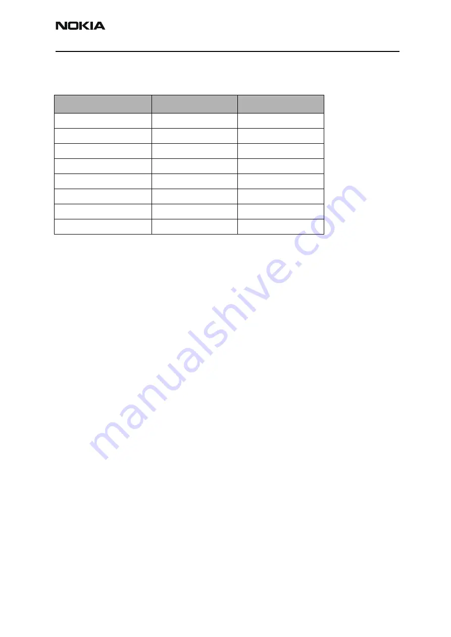
Calibration limits
Table 1: BB calibration limits
Parameter
Min
Max
ADC Offset
-50
+50
ADC Gain
26500
28500
BSI Gain
950
1100
Battery Voltage Offset
2300
2900
Battery Voltage Gain
10000
11000
Charger Voltage
55800
64000
Charger Current Offset
-150
+150
Charger Current Gain
3750
4650


