nokia
C
ONNECTING
P
EOPLE
PAGE 10 (18)
Approved 7.0
CMO Operations & Logistics
MGR
Training and Vendor Development
Multimedia Creation & Support
COMPANY CONFIDENTIAL
12.Sept.2007
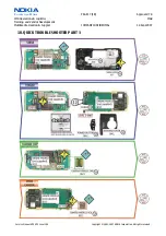
9.) Insert the SRT-6 between the
Antenna Cover
and
Chassis Assy
. Additional force may be required while
opening the
Antenna Cover
clips.
10.) Remove the
Power Button
with tweezers.
11.) Protect the
Camera Rear Bezel Assy
with a
plastic film before turning the unit.
12.) Remove the
Camera
gasket
(N70 only).
13.) Unlock and remove the
VGA Camera
with the
SS-
51
camera removal tool. (N70 only)
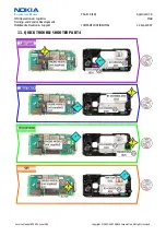
14.)
Mind the correct position when fitting the
Camera into its compartment. (N70 only)
15.) Unscrew the 6 Torx size 6 plus screws in the
shown order.
For Assembly use the reverse order
and the torque of 25 Ncm.
16.) Lift the
UI-frame Assy
from
Chassis Assy
. Mind
the still connected flex foil of the
LCD.
Service Manual N70 N72 Level 1&2
Copyright © 2005-2007 NOKIA Corporation. All rights reserved.


