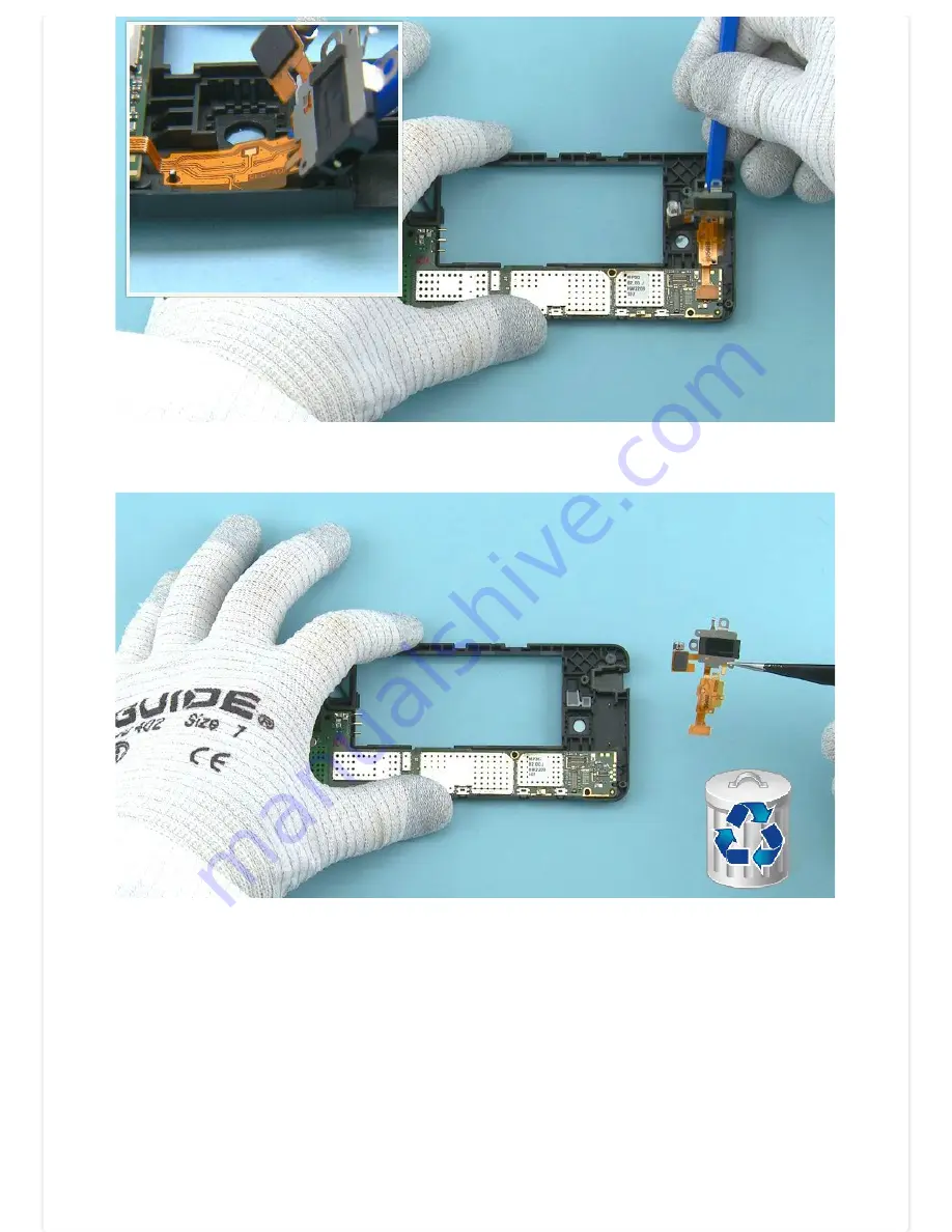
25) Push the SS-93 under the flex part as shown.
26) Remove and discard the TOP FLEX.
©2014 Nokia | Nokia Internal Use only | All Rights Reserved.
Страница 1: ...M 978 RM 979 only 4 5 LCD display 1 2 GHz Quad Core processor Version 1 0 Note Check the repair policy before performing any mechanical repair on Service Level 1 2 Exploded view Disassembly steps Assembly steps Solder components Service devices Product controls and interfaces Service concept Phone reset Proximity sensor troubleshooting More More More More More More More More More 2014 Nokia Nokia ...
Страница 2: ...1 and 2 Nokia Lumia 630 RM 976 RM 977 Nokia Lumia 630 Dual SIM RM 978 RM 979 Version 1 0 Version history Version Date Description 1 0 29 04 2014 First published version 2014 Nokia Nokia Internal Use only All Rights Reserved ...
Страница 3: ...08 TYPE LABEL I0012 EARPIECE PLATE I0003 DISPLAY I0002 EARPIECE I0004 LIGHT SWAP PACKAGE I0011 USB BOOT I0013 IHF SPEAKER I0014 IHF SPEAKER GASKET I0009 ANTENNA 3G ANTENNA LTE I0006 IHF MESH I0010 MAIN ANTENNA HOLE ADHESIVE I0021 SCREW TORX SIZE 4 RF1 4 X 3 0 I0018 SCREW TORX SIZE 4 M1 4 x 2 5 I0020 SCREW TORX SIZE 4 M1 4 x 3 4 I0019 LIGHT SWAP PACKAGE I0011 I0012 3 DISPLAY ASSEMBLY I0001 I0002 1 ...
Страница 4: ... 630 Dual SIM RM 978 RM 979 Version 1 0 Disassembly steps 1 For disassembling you need the Nokia Standard toolkit version 2 You will also need the camera removal tool SS 305 2 Protect the DISPLAY with protective film 2014 Nokia Nokia Internal Use only All Rights Reserved ...
Страница 5: ...3 Release the BACK COVER by pulling from the both top end corners as shown 4 Lift up and remove the BACK COVER 2014 Nokia Nokia Internal Use only All Rights Reserved ...
Страница 6: ...ch 6 Lift up one corner of the MAIN ANTENNA HOLE ADHESIVE with the dental tool Peel off and discard the MAIN ANTENNA HOLE ADHESIVE Be careful not to injure yourself or the device with the sharp end of the dental tool 2014 Nokia Nokia Internal Use only All Rights Reserved ...
Страница 7: ...TORX size 4 screws in the order shown Do not use them again Discard them 8 Unscrew the seven TORX size 4 screws in the order shown Do not use them again Discard them 2014 Nokia Nokia Internal Use only All Rights Reserved ...
Страница 8: ...ly release the CHASSIS ASSEMBLY from the DISPLAY ASSEMBLY Be careful not to damage the shown flex 10 Use the SS 93 to release the shown clip on the other side of the device 2014 Nokia Nokia Internal Use only All Rights Reserved ...
Страница 9: ...n be separated once the connector is opened Be careful not to bend the flex or damage the connector 12 Push the SS 93 under the EARPIECE PLATE to release it Make sure to remove all EARPIECE PLATE adhesive remains from the DISPLAY ASSEMBLY 2014 Nokia Nokia Internal Use only All Rights Reserved ...
Страница 10: ...e the EARPIECE from the EARPIECE PLATE Do not use the EARPIECE PLATE again Discard it 14 Push the sharp end of the SS 93 under the IHF SPEAKER to release it Remove it with tweezers 2014 Nokia Nokia Internal Use only All Rights Reserved ...
Страница 11: ...e the IHF SPEAKER GASKET with dental tool Remove and discard the IHF SPEAKER GASKET 16 Use the SS 93 to release the IHF MESH Remove and discard the IHF MESH 2014 Nokia Nokia Internal Use only All Rights Reserved ...
Страница 12: ... to damage the connector or any nearby components 18 Place the SS 305 camera removal tool on top of the CAMERA as shown Note the alignment Push down the SS 305 until the camera retaining clips are released Hold from the sides of the SS 305 2014 Nokia Nokia Internal Use only All Rights Reserved ...
Страница 13: ...ll up the SS 305 while holding from the sides of it and remove the CAMERA 20 Use dental tool to remove the CAMERA GASKET Do not use it again Discard it 2014 Nokia Nokia Internal Use only All Rights Reserved ...
Страница 14: ...crew the shown TORX size 4 screw Discard it 22 Open the TOP FLEX connector with the SS 93 Be careful not to damage the connector or any components nearby 2014 Nokia Nokia Internal Use only All Rights Reserved ...
Страница 15: ...23 Use the sharp end of the SS 93 to lift up the vibra as shown 24 Lift up also the AV connector 2014 Nokia Nokia Internal Use only All Rights Reserved ...
Страница 16: ...25 Push the SS 93 under the flex part as shown 26 Remove and discard the TOP FLEX 2014 Nokia Nokia Internal Use only All Rights Reserved ...
Страница 17: ...27 Lift up the ENGINE BOARD from the shown place so that the shown two clips holding it are released 28 The ENGINE BOARD can now be separated 2014 Nokia Nokia Internal Use only All Rights Reserved ...
Страница 18: ...29 Remove the USB BOOT 30 The Nokia Lumia 630 Nokia Lumia 630 Dual SIM disassembly procedure is complete END OF DISASSEMBLY 2014 Nokia Nokia Internal Use only All Rights Reserved ...
Страница 19: ...6 RM 979 Nokia Lumia 630 Dual SIM RM 978 RM 979 Version 1 0 Assembly steps 1 For assembling you need the Nokia Standard toolkit version 2 2 Remove the shown protective film from the EARPIECE PLATE 2014 Nokia Nokia Internal Use only All Rights Reserved ...
Страница 20: ...AY ASSEMBLY as shown Align the EARPIECE PLATE with the two shown guiding pins Press the EARPIECE PLATE gently to activate the adhesive 4 Remove the second EARPIECE PLATE protective film 2014 Nokia Nokia Internal Use only All Rights Reserved ...
Страница 21: ...align the EARPIECE so that the guiding pins are as shown Press the EARPIECE gently to activate the adhesive Be careful not to damage the EARPIECE pins 6 Note that this step is only for the single SIM variants Place the DUAL SIM BARRIER as shown and press it to activate the adhesive 2014 Nokia Nokia Internal Use only All Rights Reserved ...
Страница 22: ...e USB BOOT as shown 8 Place the ENGINE BOARD to the CHASSIS ASSEMBLY Press the ENGINE BOARD as shown and make sure the two shown clips are attached properly 2014 Nokia Nokia Internal Use only All Rights Reserved ...
Страница 23: ... TOP FLEX protective film 10 Place the TOP FLEX to the CHASSIS ASSEMBLY by using the two shown guiding pins Press the flex part gently to activate the adhesive 2014 Nokia Nokia Internal Use only All Rights Reserved ...
Страница 24: ...e AV connector and the vibra to their places 12 Connect the TOP FLEX connector with the SS 93 Be careful not to damage the connector or any components nearby 2014 Nokia Nokia Internal Use only All Rights Reserved ...
Страница 25: ... Push down the CAMERA from the sides of it until the camera retaining clips are fastened Be careful not to touch the CAMERA lens when pushing it down Do not push black area near the CAMERA lens autofocus mechanism is located below that black plastic and can be easily damaged 2014 Nokia Nokia Internal Use only All Rights Reserved ...
Страница 26: ...the shown protective film from the CAMERA GASKET 16 Place the CAMERA GASKET to the CHASSIS ASSEMBLY as shown Push the CAMERA GASKET to activate the adhesive 2014 Nokia Nokia Internal Use only All Rights Reserved ...
Страница 27: ... shown Make sure to place it straight as the CAMERA GASKET might move or bend and be visible in the CAMERA window if the CAMERA is placed in angle Connect the CAMERA connector Be careful not to damage the connector or any components nearby 2014 Nokia Nokia Internal Use only All Rights Reserved ...
Страница 28: ...19 Remove the shown protective film from the IHF SPEAKER GASKET 20 Place the IHF SPEAKER GASKET to its place and press it to activate the adhesive 2014 Nokia Nokia Internal Use only All Rights Reserved ...
Страница 29: ...ove the second IHF SPEAKER GASKET protective film 22 Note the IHF SPEAKER alignment when placing it Push the IHF SPEAKER gently to activate the adhesive 2014 Nokia Nokia Internal Use only All Rights Reserved ...
Страница 30: ...23 Remove the IHF MESH protective film 24 Place the IHF MESH and press it gently to activate the adhesive 2014 Nokia Nokia Internal Use only All Rights Reserved ...
Страница 31: ...AY connector Be careful not to damage the connector or any nearby components 26 Turn over the DISPLAY ASSEMBLY on top of the CHASSIS ASSEMBLY and press them so that both sides of the device are closed properly 2014 Nokia Nokia Internal Use only All Rights Reserved ...
Страница 32: ...hese seven screws are longer than the two screws shown in the next step 28 Fasten the two TORX size 4 screws in the order shown to the torque of 12 Ncm Note that these two screws are shorter than the seven screws shown in the previous step 2014 Nokia Nokia Internal Use only All Rights Reserved ...
Страница 33: ...29 Remove the shown protective film from the MAIN ANTENNA HOLE ADHESIVE 30 Place the MAIN ANTENNA HOLE ADHESIVE as shown 2014 Nokia Nokia Internal Use only All Rights Reserved ...
Страница 34: ...1 Press the MAIN ANTENNA HOLE ADHESIVE to activate the adhesive Remove the protective film from the MAIN ANTENNA HOLE ADHESIVE 32 Place the BATTERY 2014 Nokia Nokia Internal Use only All Rights Reserved ...
Страница 35: ...to the BACK COVER bottom end first Press the DISPLAY ASSEMBLY to attach it properly to the BACK COVER The Nokia Lumia 630 Nokia Lumia 630 Dual SIM assembly procedure is complete 2014 Nokia Nokia Internal Use only All Rights Reserved ...
Страница 36: ... X1002 X1003 X2001 X2104 X2105 X6301 X7720 X7721 X7722 Camera fuse Power Lock key Volume key Volume key Grounding spring Grounding spring Grounding spring Grounding spring Battery connector IHF Speaker spring IHF Speaker spring BT WLAN spring GNSS spring Main antenna spring Keyboard LED TOP BOTTOM 2014 Nokia Nokia Internal Use only All Rights Reserved ...
Страница 37: ... AC 20 AC 21C Only for China SS 305 Camera removal tool BL 5H Battery Nokia Standard Toolkit v2 For more information refer to the Service Bulletin SB 011 on Nokia Online Supplier or manufacturer contacts for tool re order can be found in Recommended service equipment document on Nokia Online 2014 Nokia Nokia Internal Use only All Rights Reserved ...
Страница 38: ...79 Version 1 0 Product controls and interfaces 3 2 1 8 7 9 10 4 5 11 6 8 Volume key 7 Volume key 6 Camera 5 Micro USB connector 4 Microphone 3 Touch screen 2 Earpiece 1 3 5 mm AHJ connector 9 Power Lock key 10 Loudspeaker 11 Main antenna area 2014 Nokia Nokia Internal Use only All Rights Reserved ...
Страница 39: ... Nokia Lumia 630 RM 976 RM 977 Nokia Lumia 630 Dual SIM RM 978 RM 979 Version 1 0 Service concept Flashing concept CA 101 Service software Transceiver Product specific battery 2014 Nokia Nokia Internal Use only All Rights Reserved ...
Страница 40: ...ld the volume down key 4 Exclamation mark is shown on the screen release the volume down key Software operating system OS reset The software operating system OS reset returns the phone to its out of the box state Note that this procedure erases all consumer data Always first try to perform a hardware reset Option 2 Hardware key combination Use this option if the phone is locked and the consumer do...
Страница 41: ...Step 2 Input the following key combination 1 Volume up 2 Volume down 3 Power 4 Volume down Step 3 The phone will reset and boot up automatically 2014 Nokia Nokia Internal Use only All Rights Reserved ...
Страница 42: ...ne touch screen becomes unresponsive use a cleaning cloth to wipe the touch screen clean To avoid scratches on display do not use anything that could scratch the display and do not use chemicals for cleaning 2 Advice the customer that two short power key presses wake up the display if it stays black in situation where is should be active 3 Check that latest Phone SW is in use That has the best pro...
Страница 43: ... Advice the customer that protective foils may affect the functionality of the touch screen Touch screen functions or proximity sensing may be affected by humidity rain drops make up or dirt on the display If your phone touch screen becomes unresponsive use a cleaning cloth to wipe the touch screen clean To avoid scratches on display do not use anything that could scratch the display and do not us...