background image

OPERATION

Nobles

 Tuff Scrub

 3300 (09–9

7

MACHINE INSTALLATION

UNCRATING MACHINE

1.

Carefully check crate and machine for signs of
damage. Report damages at once to carrier.

2.

Check Machine Contents list, contact distributor
for missing items.

Machine Contents:

– 

5 Battery Cables (stored in battery
compartment)

Squeegee Assembly (bolted on shipping pallet)

6 Batteries, 335A 6V (included with Pac
606994; not included with Pac 609237)

Battery Charger (included with Pac 606994 &
609237)

2 Pad Drivers  (included with Pac 606994 &
609237)

Scrub brushes and pads must be purchased
separately (See PARTS LIST section).

3.

To uncrate your machine:

a.

Remove shipping straps.

b.

Install batteries if not pre–installed (See
INSTALLING BATTERIES)

c.

Remove rear wheel block from pallet.

d.

Position ramp (supplied) at rear of machine,
release parking brake and carefully back
machine off pallet (See MACHINE
OPERATION).

ATTENTION: Do not roll machine off pallet without
using ramp, machine damage may occur.

INSTALLING BATTERIES

WARNING: Batteries emit hydrogen gas.

Explosion or fire can result. Keep sparks and
open flame away.

FOR SAFETY: When servicing machine, wear
hand and eye protection when handling batteries
and battery cables. Avoid contact with battery
acid.

Recommended Battery Specifications:
Six 6 volt, deep cycle, 335 amp. hour batteries.
Maximum battery dimensions are 179 mm (7.00 in) W
x 296 mm (11.66 in) L x 424 mm (16.69 in) H.

1.

Turn key to the off position.

2.

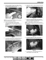
Set parking brake pedal. Press brake pedal
completely forward then press parking brake pedal
with toe to set (Fig. 1).

Figure 1

FOR SAFETY: Before leaving or servicing
machine, stop on level surface, set parking brake,
turn off machine and remove key.

3.

Hinge seat away from machine to access battery
compartment. Remove loose battery cables from
compartment (Fig. 2).

Figure 2

4.

Carefully install batteries into battery compartment
and arrange battery posts as shown (Fig. 3).

Machine
Front

R
E
D

BLACK

1

2

3

4

5

7

6

Figure 3

ATTENTION: Do not drop batteries into
compartment, battery and machine housing
damage may result. This damage is not covered
by warranty.

Home

Find...

Go To..

Содержание Tuff Scrub 3300

Страница 1: ...Scrub 3300 Model No 606993 606994 Pac 609237 Can Pac Operator and Parts Manual 608596 Rev 01 06 00 CUSTOMER SERVICE 1 800 365 6625 FAX 1 800 678 4240 NOBLES 12875 RANSOM STREET HOLLAND MI 49424 U S A...

Страница 2: ...TABLE OF CONTENTS SAFETY PRECAUTIONS 3 SAFETY LABELS 4 MACHINE COMPONENTS 5 CONTROL CONSOLE SYMBOLS 6 MACHINE INSTALLATION 7 UNCRATING MACHINE 7 INSTALLING BATTERIES 7 MACHINE SETUP 8 ATTACHING SQUEEG...

Страница 3: ...3 When using machine Go slow on inclines and slippery surfaces Use care when reversing machine Do not carry riders on machine Always follow safety and traffic rules Report machine damage or faulty ope...

Страница 4: ...ated on control console WARNING Batteries emit hydrogen gas Explosion or fire can result Keep sparks and open flame away FOR SAFETY Read manual before operating machine WARNING Flammable materials can...

Страница 5: ...ush Switch 9 Horn Button 10 Squeegee Vacuum Switch 11 Solution Control Knob 12 Solution Low Indicator Light 13 Power Kill Button 14 Directional Pedal 15 Brake Pedal 16 Parking Brake Pedal 17 Charger P...

Страница 6: ...wn Solution On Brush Motor RH 30A Circuit Breaker Main Power 10A Circuit Breaker Horn Brush Motor LH 30A Circuit Breaker Vacuum Motor 30A Circuit Breaker Drive Motor 35A Circuit Breaker Key Switch Sol...

Страница 7: ...ne damage may occur INSTALLING BATTERIES WARNING Batteries emit hydrogen gas Explosion or fire can result Keep sparks and open flame away FOR SAFETY When servicing machine wear hand and eye protection...

Страница 8: ...pedal completely forward then press parking brake pedal with toe to set Fig 1 FOR SAFETY Before leaving or servicing machine stop on level surface set parking brake turn off machine and remove key 3 L...

Страница 9: ...ig 8 Figure 8 INSTALLING BRUSHES PAD DRIVERS NOTE Consult an authorized distributor for brush pad recommendations 1 Turn key to the on position and press brush switch to raise scrub head Fig 9 Figure...

Страница 10: ...clean water 60 C 140 F maximum Fig 13 Solution tank capacity is 151 L 40 gal Figure 13 WARNING Flammable materials can cause an explosion or fire Do not use flammable materials in tank s 4 Add a recom...

Страница 11: ...m flow when starting out Then adjust to a desired flow rate after scrubbing speed is determined Fig 17 Figure 17 6 Press brake pedal to release parking brake pedal Fig 18 Figure 18 7 Press top of dire...

Страница 12: ...tank if excessive foam appears ATTENTION Do not allow foam or water to enter float shut off screen vacuum motor damage will result not covered by warranty Foam will not activate float shut off screen...

Страница 13: ...tor Circuit Breaker 30A Brush Motor Circuit Breaker 2 Figure 25 HOUR METER The hour meter records number of scrubbing hours the machine has performed Use hour meter to determine when to perform recomm...

Страница 14: ...lug securely and return hose in clip 7 When finished scrubbing perform the Daily Maintenance procedures See MACHINE MAINTENANCE REMOVING BRUSHES PAD DRIVERS Brushes should be replaced when bristles ar...

Страница 15: ...ervicing machine stop on level surface set parking brake turn off machine and remove key 3 Hinge seat away from machine to access battery compartment 4 Check fluid level A in each battery cell before...

Страница 16: ...aner and damp cloth ATTENTION Do not power spray or hose off machine Electrical component damage due to water is not covered by warranty 9 Recharge batteries See CHARGING BATTERIES NOTE Recharge batte...

Страница 17: ...to fluid expansion Fig 37 A Figure 37 3 Keep battery tops and terminals clean and dry To clean batteries a Mix a strong solution of baking soda and water Fig 38 Figure 38 b Brush solution sparingly ov...

Страница 18: ...urn hex link adjuster clockwise to increase or counter clockwise to reduce brake pressure LEFT SIDE Turn hex link adjuster counter clockwise to increase or clockwise to reduce brake pressure NOTE Brak...

Страница 19: ...oor 7 Set parking brake and place a block behind each drive wheel and steering wheel 8 Place tie down straps over top of bumper wheel brackets STORING MACHINE 1 Charge batteries before storing Never s...

Страница 20: ...Center Vacuum motor will not turn on Faulty vacuum squeegee switch Contact Service Center Squeegee is raised off floor Lower squeegee Main circuit breaker has tripped Determine cause and reset circuit...

Страница 21: ...queegee thumbscrews Tighten thumbscrews Vacuum hose connections are loose or hose has a hole Push hose cuffs firmly on connections Replace hose if damaged Clogged vacuum hose Remove clogged debris Rec...

Страница 22: ...p MAXIMUM RATED CLIMB OR DESCENT Scrubbing 4 Transporting 12 TURNING RADIUS 1295 mm 51 in SPEED Forward 6 4km h 0 4 0mph Reverse 2 4km h 0 1 5mph CLEANING RATE MAX 5400 m2 58 000 sq ft per hour PAD PR...

Страница 23: ...MOTOR W H T B R N G R N O R G B L K B L K W H T W H T G G 3 4 1 MAIN CIRCUIT BREAKER 3 BLK 120 GRN BLK YEL 124 BLU 54 RED 128 GRN 56 GRN 140 GRN 102 GRN GRN WHT 52 RED RED ORG RED 46 RED 36 RED 59 BLK...

Страница 24: ...GRN RED 138 GRN GRN 24 71 BLK BLK 68 GRN BLK 82 GRN 132 GRN 24 GRN 90 GRN 79 BLK 88 GRN 19 BLK 102 GRN 138 GRN 86 9 BLK 33 64 37 WHT 66 ORG BLK 16 73 BLK 9 GRN GRN 16 BLK GRN BLK 12 86 GRN 134 GRY 10...

Страница 25: ...A BLK YEL GRN ORG 13C BLK 31 BLU BRN 34 39 BLK 120 GRN 114 RED 47 BLK 40 TAN 55 BLK BLK 33 YEL BLK 53 65 WHT 64 RED RED 36 80 BLU 15 BLK 53 BLK 46 RED 36 RED 59 BLK 54 RED 48 TAN RED 80 BLU BLK BRN GR...

Страница 26: ...UP 29 1 3 2 4 5 6 17 18 9 10 7 8 11 14 15 16 18 17 19 21 24 23 22 20 25 24 23 22 26 2 7 8 27 28 30 31 33 32 34 7 2 35 7 2 7 8 36 37 31 30 29 38 35 2 12 13 17 18 39 40 41 49 50 51 52 53 43 42 44 45 46...

Страница 27: ...LATCH 1 29 140000 WASHER 1 4 FLT 8 30 140016 WASHER 1 4 LCK 8 31 578187000 SCREW M6X1 0X12 8 ASSEMBLY INCLUDED IN ASSEMBLY RECOMMENDED STOCK ITEMS REF PART DESCRIPTION QTY 32 607037 PANEL FLOOR LEFT R...

Страница 28: ...PARTS LIST s Tuff Scrub 3300 06 00 28 CONTROL CONSOLE GROUP 1 13 5 4 6 7 8 9 11 10 14 16 17 15 18 14 19 20 21 12 2 22 3 Home Find Go To...

Страница 29: ...H BRUSH PRESSURE 1 10 626128 SWITCH PUSHBUTTON 1 11 140756 SCREW 6 32X1 4 2 12 607104 COVER STEERING BEARING 1 ASSEMBLY INCLUDED IN ASSEMBLY RECOMMENDED STOCK ITEMS N S NOT SHOWN REF PART DESCRIPTION...

Страница 30: ...PARTS LIST s Tuff Scrub 3300 06 00 30 ELECTRICAL PANEL GROUP 1 2 3 4 5 6 7 8 9 10 11 12 13 14 16 17 18 19 20 21 22 23 25 24 26 27 31 28 29 30 32 34 35 33 37 38 39 15 36 4 42 40 42 41 Home Find Go To...

Страница 31: ...R 1 4 FLAT 4 21 606780 BREAKER CIRCUIT 30A 3 22 130739 BREAKER CIRCUIT 60A 1 23 130737 BREAKER CIRCUIT 10A 1 ASSEMBLY INCLUDED IN ASSEMBLY RECOMMENDED STOCK ITEMS N S NOT SHOWN REF PART DESCRIPTION QT...

Страница 32: ...uff Scrub 3300 06 00 32 RECOVERY TANK GROUP 13 2 1 29 17 9 6 7 8 10 9 14 15 16 11 12 19 21 22 26 17 18 11 23 38 14 18 28 24 21 6 25 16 27 30 31 18 17 33 32 37 36 35 34 17 18 20 18 3 4 5 29 39 28 29 Ho...

Страница 33: ...1 4 LOCK 7 17 140015 WASHER 5 16 SPLTLCK 9 18 140275 SCREW M8X1 25X16 HXHDCP 18 19 600877 HINGE RECOVERY TANK 1 20 140027 WASHER 5 16 FLAT 9 ASSEMBLY INCLUDED IN ASSEMBLY RECOMMENDED STOCK ITEMS REF P...

Страница 34: ...PARTS LIST s Tuff Scrub 3300 09 99 34 SEAT GROUP 1 2 3 4 5 6 7 8 9 10 11 12 13 14 15 17 17 18 19 20 21 22 23 24 25 16 Home Find Go To...

Страница 35: ...UT 5 16 18 HEX 4 11 607404 DECAL TUFF SCRUB 3300 1 12 607834 DECAL BATT HOOKUP 1 13 120649 DECAL WARNING BATTERY 1 RECOMMENDED STOCK ITEMS REF PART DESCRIPTION QTY 14 630420 DECAL WARNING BATTERY 1 15...

Страница 36: ...PARTS LIST s Tuff Scrub 3300 09 99 36 CHARGER AND BATTERY GROUP 1 2 3 4 6 5 Home Find Go To...

Страница 37: ...P REF PART DESCRIPTION QTY 1 602004 CHARGER 36DC 36A 120V AC 1 2 601733 BATTERY 6V 335AH 6 3 140506 NUT 5 16 18 HEX 12 ASSEMBLY INCLUDED IN ASSEMBLY REF PART DESCRIPTION QTY 4 611117000 CABLE BATTERY...

Страница 38: ...uff Scrub 3300 09 99 38 STEERING GROUP 1 11 2 3 4 5 6 5 7 5 8 9 10 23 12 13 14 12 16 15 17 18 19 20 21 22 10 25 24 28 34 28 33 29 32 28 29 30 27 26 28 29 31 27 26 35 36 37 39 40 38 41 42 43 10 28 44 H...

Страница 39: ...AM 2 20 140515 NUT 3 8 16 NYLCK 1 21 607838 STUD 3 8 16X4 1 22 140545 NUT 3 8 16 FINJAM 1 23 200031541 SCREW 10X25 1 REF PART DESCRIPTION QTY 24 607071 SPACER 1 25 600924 WASHER BEARING 2 26 605943 SL...

Страница 40: ...Tuff Scrub 3300 06 00 40 MAIN FRAME AND DRIVE GROUP 40 39 38 41 42 44 41 42 43 5 6 7 8 13 12 14 13 15 16 17 19 16 18 20 21 23 22 24 25 22 26 27 28 30 33 32 31 37 36 35 29 9 10 11 10 11 9 1 3 4 2 34 Ho...

Страница 41: ...2 24 606985 WHEEL 10 REAR STEERING 2 25 140028 WASHER 3 8 FLT 2 26 140333 WASHER M10 SPLTLCK 2 REF PART DESCRIPTION QTY 27 140276 SCREW M10X1 5X16 2 28 069767162 NUT HEX 6 29 140024 WASHER 1 2 LCK 6...

Страница 42: ...06 00 42 CONTROL GROUP 39 1 2 3 4 5 7 8 9 10 11 12 15 13 14 49 18 9 17 20 4 19 3 21 21 2 22 23 24 25 27 26 28 22 37 35 9 22 22 30 33 22 36 22 29 31 42 22 36 43 40 41 38 6 37 32 34 16 36 3 44 44 45 47...

Страница 43: ...BRAKE 1 22 140028 WASHER 3 8 FLT 8 23 200031552 SCREW M10X1 5X55 1 24 579082 SPACER 38X 50X1 00 1 ASSEMBLY INCLUDED IN ASSEMBLY RECOMMENDED STOCK ITEMS REF PART DESCRIPTION QTY 25 604605 SPRING TORSIO...

Страница 44: ...0 06 00 44 PAD DRIVER GROUP 33 2 1 3 4 5 11 10 12 7 6 13 14 15 16 17 8 9 18 19 20 21 22 23 25 23 26 21 28 30 23 26 32 35 34 36 37 38 40 39 41 23 34 23 42 43 44 45 46 24 31 27 23 29 26 21 28 30 23 23 2...

Страница 45: ...045 WASHER 510X1 25X 06 FLT 26 24 200031441 SCREW M6X1 0X25 2 25 140234 SCREW 1 2 13X2 1 2 2 ASSEMBLY INCLUDED IN ASSEMBLY RECOMMENDED STOCK ITEMS N S NOT SHOWN REF PART DESCRIPTION QTY 26 140516 NUT...

Страница 46: ...ff Scrub 3300 06 00 46 SOLUTION GROUP 1 2 3 4 5 7 6 9 10 11 14 13 8 15 16 17 18 19 20 21 22 23 24 25 2 2 2 2 2 2 2 2 2 42 42 29 39 41 38 41 39 41 28 27 26 36 42 35 42 33 40 34 37 42 42 31 30 32 12 41...

Страница 47: ...4M X 3 4H 1 19 160229 TUBING VINYL 3 4 ID X 1 OD 75ft 20 607832 FITTING 3 8MPT X 3 4H 1 21 607075 BRACKET FILTER MOUNT 1 ASSEMBLY INCLUDED IN ASSEMBLY RECOMMENDED STOCK ITEMS REF PART DESCRIPTION QTY...

Страница 48: ...PARTS LIST s Tuff Scrub 3300 06 00 48 SKIRT GROUP 1 2 3 4 5 6 7 8 10 9 4 6 5 7 11 16 22 19 20 17 15 13 12 14 12 21 21 10 9 5 6 4 4 6 5 22 8 22 18 Home Find Go To...

Страница 49: ...2 9 607407 SPLASH GUARD SKIRT 2 10 600911 BLADE SKIRT SQUEEGEE 2 11 607408 STRAP SPLASH GUARD 2 RECOMMENDED STOCK ITEMS REF PART DESCRIPTION QTY 12 140007 WASHER 8 FLT 22 13 579237 SCREW M4X 7X12 PANP...

Страница 50: ...PARTS LIST s Tuff Scrub 3300 06 00 50 SQUEEGEE CONTROL GROUP 1 2 3 3 4 5 6 7 8 9 5 3 3 13 12 11 28 14 15 16 15 17 15 15 17 6 3 8 19 20 22 21 23 18 24 25 26 27 7 3 5 6 29 10 30 31 30 16 Home Find Go To...

Страница 51: ...1 12 140232 SCREW 3 8 16X1 1 4 2 13 140545 NUT 3 8 16 FINJAM 2 14 607123 ROD SQ CENTERING 1 15 607124 SPRING COMP 4 16 140028 WASHER 3 8 FLT 2 RECOMMENDED STOCK ITEMS REF PART DESCRIPTION QTY 17 1405...

Страница 52: ...00 52 SQUEEGEE GROUP 2 3 6 7 8 10 1 11 32 13 14 15 16 17 19 20 22 11 17 17 17 16 8 20 20 19 19 23 14 12 23 13 15 6 10 7 19 20 19 20 29 18 30 25 9 27 28 24 25 26 19 20 29 27 28 9 18 30 25 24 25 26 31...

Страница 53: ...X3 4 2 16 222497 BUSHING 318 X 495 X1 25 2 17 370100 KNOB 5 16 THD BLACK 4 ASSEMBLY INCLUDED IN ASSEMBLY RECOMMENDED STOCK ITEMS REF PART DESCRIPTION QTY 18 384491 STRIP SQUEEGEE CORNER PLATE 2 19 140...

Отзывы: