background image

14

15

2.5. UPS installation for parallel system

If the UPS is only available for single operation, you may skip this section to 

the next.

  Step 1.

  Install and wires the UPS according to the section 2.3

  Step 2.

  Connect the output wires of each UPS to an output breaker.

  Step 3.

   Connect all output breakers to a major output breaker. Then this 

major output breaker will directly connect to the loads.

  Step 4.

   Common battery packs or independent battery packs are 

allowed.

  Step 5.

  Refer to the following wiring diagram:

Wiring diagram of parallel system for Ranger 180KT

Check section 3.5. for Parallel operation of UPS.

2.6. Software installation

For optimal computer system protection, install UPS monitoring software 

from 

https://www.power-software-download.com/viewpower.html

.

Operations

3

3.1. Initial operation

  Step 1.

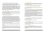
  Before operation, make sure that the two strings of batteries 

are connected correctly  in order     of ”+,GND,-” terminals and the breaker 

of the battery pack is at “ON” position (only in case of external battery packs 

presence).

  Step 2.

  Press the   

POWER

 button to set up the power supply for the 

UPS. UPS will enter to power on mode. After initialization, UPS will enter to 

“No Output mode”.

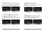
3.2. Screen description

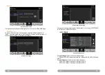
After initialization, the LCD will display main screen. 

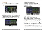
There are five sub-menus: Control, Measure, Setting, Information and Data log. 

Touch any sub-menu icon to enter into the sub-screen.

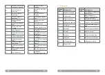
Main

Control

Measure

Setting

Info

Data Log

ON/OFF UPS

ON/OFF charger

Battery test

Mute all

Measure 1

Measure 2

Measure 3

Save setting

General

Advance

Basic 1

Basic 2

Electrical

Battery

Miscellaneous

Electrical

Battery

Miscellaneous

UPS self-test

SYS parameter

Install info

VOL CALLI

CURR CALLI

Initial

Data log

Parameters

Calibration

EEPROM

Touch

User

Maintainer

Basic info

Rated info

Parameter info

User mode 

Password: 0000

Maintaner mode 

Password: ****

Содержание Ranger 180KT

Страница 1: ...Ranger Series User Manual 180KT 3 Phase IN 3 Phase OUT UPS UP33TOP118ZRAAZ01B 237 35 21 0 Before using this product carefully read all product documentation and retain it for future reference...

Страница 2: ...EMC instructions 5 1 1 Transportation and storage 5 1 2 Preparation 5 1 3 Installation 5 1 4 Connection warnings 6 1 5 Operation 7 1 6 Standards 7 2 Installation and operation 8 2 1 Unpacking and insp...

Страница 3: ...lation An integral emergency shutoff switch which prevents additional load from the UPS in any mode of operation should be implemented during the installation Secure the grounding earthing wire before...

Страница 4: ...ee phase input NOTE There can be no derivation in the line that goes from the Backfeed Protection to the UPS as the standard safety would be infringed Warning labels should be placed on all primary po...

Страница 5: ...t and battery set in their original packaging because they have been designed to provide maximum protection during transportation and storage Installation and operation 2 2 2 Wiring terminal view 1 RS...

Страница 6: ...the output power will be derated by following the table Vertical No vibration and the degree of deviation from vertical shouldn t be more than 5 Space It s requested to have a clearance of approx 50 c...

Страница 7: ...l block wiring diagram for HV 180KT NOTE Please install the output breaker between the output terminal and the load and the breaker should be qualified with leakage current protective function if nece...

Страница 8: ...ration make sure that the two strings of batteries are connected correctly in order of GND terminals and the breaker of the battery pack is at ON position only in case of external battery packs presen...

Страница 9: ...that takes a few seconds After initialization the main screen will display as shown below On the bottom there are five icons to represent five sub menus CONTROL MEASURE SETTING INFO DATALOG Main scree...

Страница 10: ...te All if the UPS is mute already Touch Yes activate audio function or No to keep mute Touch Back to return to CONTROL screen Mute All Cancel Mute All ON OFF Charger It will show Turn on Charger when...

Страница 11: ...al time value of output power factor in R S and T phases 3 2 4 Setting screen This sub menu is used to set the parameters of UPS Touch the icon to enter setting menu page There are 2 options Basic and...

Страница 12: ...the acceptable input frequency will be fixed at the range of 40 70Hz This setting value will show on the status bar Service Contact Set the name of contact person and the maximum length is 18 characte...

Страница 13: ...sword is wrong it will ask to enter again Password error page Advance Setting Menu page There are three sub menus under Advance User setting ELECTRONIC BATTERY and MISCELLANEOUS ELECTRONIC Electronic...

Страница 14: ...When neutral is restored the alarm will NOT be muted automatically and the UPS will NOT go back to normal mode automatically ISO Compensation When UPS is connected to output isolation it will compensa...

Страница 15: ...then utility restores the UPS will return to line mode Disable After Disable is set once UPS shutdown occurs and the utility restores the UPS will not automatically turn on Shutdown Delay Min UPS wil...

Страница 16: ...ble ECO function Auto Restart Enable disable auto restart function PARAMETER information Parameter Information Page1 Line Voltage Range The acceptable line input voltage range Line FRE Range The accep...

Страница 17: ...S operates in Bypass mode and supplies power to the load via the bypass NOTE When UPS is in Bypass mode the output voltage will draw power from utility after you switch on the input breaker In Bypass...

Страница 18: ...may vary from different environment temperature and load type When setting backup time for 16 5 hours default value from LCD menu after discharging 16 5 hours UPS will shut down automatically to prote...

Страница 19: ...nician that installed the UPS if you need to start parallel operations 3 5 1 Parallel system initial startup Please make sure that all of the running UPSs are parallel models and have the same configu...

Страница 20: ...d in each UPS and then turn off the running system All UPSs will transfer to Bypass mode Remove all the maintenance bypass covers and set the maintenance switches from UPS to BPS position Turn off all...

Страница 21: ...current in A phase 34 Synchronous trigger signal failure 75 INV IGBT over current in B phase 35 Parallel communication loss 76 INV IGBT over current in C phase 36 Parallel output current unbalance 77...

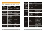
Страница 22: ...UPS output and restart it Troubleshooting 4 Problem Possible cause Solutions Fault code is shown as 14 15 16 17 18 or 19 The UPS shut down automatically because short circuit occurs on the UPS output...

Страница 23: ...capacitor such as BUS capacitors Only persons adequately familiar with batteries and with the required precautionary measures may replace batteries and supervise operations Unauthorized persons must...

Страница 24: ...nt By ensuring this product is disposed of correctly you will help prevent potential negative consequences for the environment and human health which could otherwise be caused by inappropriate waste h...

Страница 25: ......
Отзывы: