


Nixie Tube Clock ‘SixNix’
Issue 5 (14 August 2012)
www.pvelectronics.co.uk
- 12 -
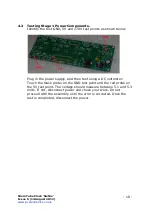
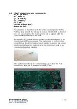
4.4 High Voltage Generator Test.
- Refer to the warnings on page 4
- Insert IC2 into its socket. Orient the notch on the IC with the
notch on the IC socket and the PCB marking.
- Power up the PCB, and using the GND and 170V test points,
measure the high voltage generated. It should be between 167 and
173V. Disconnect the power supply.
- Finally, remove IC2 from its socket and replace on its static-
protective foam. It is best kept safe until needed for the tube tests
later in the assembly.
- If you do not get this voltage, disconnect the power supply and
check your work carefully. Do not proceed until you get the correct
voltage at this stage.
Содержание SixNix
Страница 29: ...Nixie Tube Clock SixNix Issue 5 14 August 2012 www pvelectronics co uk 29 10 CIRCUIT DIAGRAM ...
Страница 30: ...Nixie Tube Clock SixNix Issue 5 14 August 2012 www pvelectronics co uk 30 ...
Страница 31: ...Nixie Tube Clock SixNix Issue 5 14 August 2012 www pvelectronics co uk 31 10 DIMENSIONED DRAWING ...


