

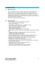


Nixie Tube Clock ‘SixNix’
Issue 5 (14 August 2012)
www.pvelectronics.co.uk
- 11 -
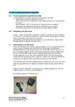
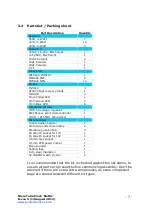
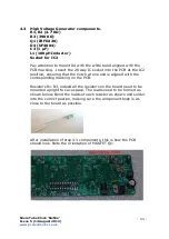
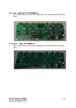
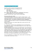
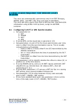
4.3
High Voltage Generator components.
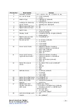
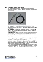
R1, R2 (4.7 KΩ)
R3 (390 KΩ)
Q1 (IRFD220)
D4 (UF4004)
C3 (1 µF)
L1 (100µH Inductor)
Socket for IC2
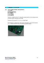
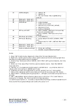
Pay attention to mount D4 with the white band aligned with the
PCB marking. Insert the 28 way IC socket into the PCB at the IC2
position, ensuring that the notch at one end is aligned with the
corresponding marking on the PCB.
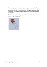
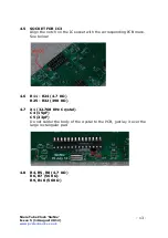
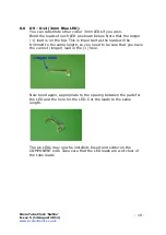
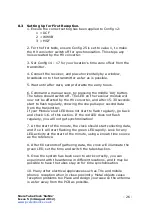
Resistors R1-R3, indeed all the resistors on the board need to be
mounted upright to save space. The leads need to be formed as
shown below. Bend the leads of each resistor as shown and solder
into the correct postion, making sure the component body is as
close to the board as possible.
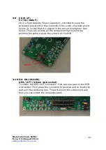
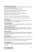
After installation of step 4.3 components, this is how the PCB
should look. Note the orientation of MOSFET Q1:
Содержание SixNix
Страница 29: ...Nixie Tube Clock SixNix Issue 5 14 August 2012 www pvelectronics co uk 29 10 CIRCUIT DIAGRAM ...
Страница 30: ...Nixie Tube Clock SixNix Issue 5 14 August 2012 www pvelectronics co uk 30 ...
Страница 31: ...Nixie Tube Clock SixNix Issue 5 14 August 2012 www pvelectronics co uk 31 10 DIMENSIONED DRAWING ...


