9
/
14
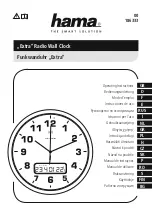
the board, observing the blue mark on one side of the pins. Make sure the blue side
is facing a line mark on the board as shown on the picture above.
Please check the board and make sure the parts are soldered correctly. Then connect
the power adapter and watch that six LEDs light up. The buzzer will make
a“Beep”
sound when the
Power button
of IR remote controller is pressed.
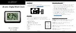
Assembly of IV-11 tubes
The following components are needed:
Name
Description
Designator
Qty
Value
Notice
VFD tubes
IV1, IV2, IV3, IV4, IV5, IV6
6
VFD tube spacer
Laser cut
12
Please straighten all pins of tubes, then put pins through two tube spacers(please
remove the protective film and clear all small holes), and solder the tubes on the board
following the pictures below:
Assembly electronic components