


6
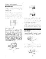
6-2. Sanding Pressure
Sanding pressure for FS-100C is 20 to 50 N and
for FS-50A is 10 to 30 N. Applying excessive force
will lower sanding efficiency. For flat work, adjust
pressure so force is applied evenly to the entire
surface of the Rubber Pad. Uneven pressure will
result in an irregular surface.
7. REPLACING RUBBER SUPPORTS
WARNING
Always turn off the air supply and disconnect the
air supply hose beforehand whenever replacing
Rubber Supports.
7-1. FS-100C
Disassembly Sequence
1) Place the Trigger at OFF, loosen 4 screws (Cross
Pan Head Screw with Spring Lock Washer M4 x 10)
and remove the Rubber Pad. Loosen 4 nuts of the
Rubber Support and remove the Base Plate.
NOTE:
Do not remove the air tube.
2) Loosen 4 screws (Cross Recessed Pan Head
Tapping Screw M4 x 20) and remove the Housing
Cover. (Fig. 8) Trigger and the Cancel Switch can
be also taken off same time.
Fig. 8
3) Loosen 4 nuts of the Rubber Support and take
out 4 Rubber Supports from the Housing. Now the
disassembly is completed. (Fig.9)
Fig. 9
Assembly Sequence
1) Fix 4 Rubber Supports to the Housing with the nuts.
Place the Trigger and the Cancel Switch and spring
0.45 x 3.1 x 17 on the Housing, and mount the
Housing Cover on them, and tighten 4 screws (Cross
Recessed Pan Head Tapping Screw M4 x 20).
2) Fix the Base Plate to the Rubber Supports with 4
nuts, taking care to prevent the Rubber Support
from being twisted.
NOTE:
If the Rubber Support is installed, being
twisted, the Rubber Support will be quickly
damaged. (Fig.9)
3) T h e r e a f t e r, r e a s s e m b l e i n t h e r e v e r s e o f
disassembly.
NOTE:
If the screws are not tightened securely, they will
become loose due to vibration, leading to parts
damage. Therefore, tighten them sufficiently.
7-2. FS-50A
Disassembly Sequence
1) Loosen 4 screws (Cross Recessed Pan Head Screw
with Spring Lock Washer M4 x 8) and remove the
Rubber Pad. (Fig.10)
Fig. 10
2) Loosen Cross Recessed Countersunk Fiat Head
Screw M6 x 14 of the Base Plate and remove the
Base Plate from the End Plate. (Fig.10)
NOTE:
Do not remove the air tube.
3) Loosen the screws at both sides of the Rubber
Support and remove the Rubber Support. Now the
disassembly is completed. (Fig.11)
Fig. 11
Assembly Sequence
First, install the Rubber Support to the Housing by
screws (Cross Recessed Pan Head Screw with
Toothed Lock Washer M4 x 8). Next, fit the End
Plate by screws (Cross Recessed Countersunk Flat
Head Screw M4 x 6), grasping lightly the bottom of
the Rubber Support with pliers, etc. and taking care
to prevent the Rubber Support from being twisted.
Содержание FS-100C
Страница 11: ......


