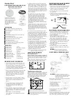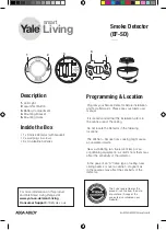
INSTALLATION
1. Connect the wires to the mounting base.
2. Select a proper place (normally mounted on the center of
ceiling). Fix the mounting base and then put the detector into
the base and twist to fasten it.
CONNECTION DESCRIPTION
1. 2 wire smoke detectors: base terminals “1” and “2” for DC power
input, non-polarized. When remote indicator is used, “1” in must be
connected to the positive line in. “4” for DC power positive output.
“3” for remote indicator cathode.
2. 4 wire smoke detectors: base terminals “1” and “2” for DC power
input, non-polarized. “3” for relay output N.C. or N.O., “4” for relay
output com.
WIRE DIAGRAM
2 WIRE BASE TERMINALS
2. POWER (-) INPUT 3. REMOTE LED OUTPUT
1. POWER (+) INPUT 4. POWER (+) OUTPUT
4 WIRE BASE TERMINALS
2. POWER (-) INPUT 3. RELAY OUTPUT (N.O.)
1. POWER (+) INPUT 4. RELAY OUTPUT (COM)
NOTICE
1.The detector can’t be installed under worse environment.
E.g.: coldest, hottest, dusty, do not move away the dustproof
cover until use the detector indeed.
2. Make sure that there is no block within 0.5m from detector.
3. Keep the distance between detector and wall more than 0.5m.
4. Make sure the distance between detectors be less than 15m. And
the distance between detector and corner must be less than half
of the one between detectors.
5. Horizontally install the detector. If have to be installed
slantingly, please keep the angle less than 45 degrees.
6. Base be installed solid, wire connection must be reliable.
7. Recommendations should be carried out every six months a
simulated fire test, the test detectors are working properly.
8. For various reason, including, but not limited to changes in
environmental conditions, electric disruptions and tampering,
the product may not perform as expected. The user is advised
to take all necessary precautions for his/her safety and the
protection of his/her property.


