58
Service Manual – SW5500, FLOORTEC R 985
05 - Control System
Specifications
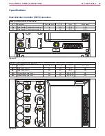
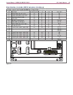
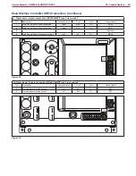
Main Machine Controller (EB1) Connectors
Battery Connection (M6 screw terminals)
Ref.
Description
Controller in/out
V ref.
I max.
Connected to
B+
Main Machine Controller power
in
24V
150A
BAT+
B-
Main Machine Controller power supply -
in
0V
150A
BAT-
B+
B-
Figure 23:
B-
B+
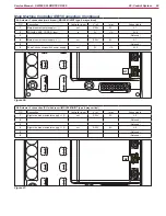
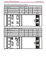
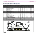
Power Connections (M5 screw terminals)
Ref.
Description
Controller in/out
V ref.
I max.
Connected to
BR+
Main broom motor +
out
24V
120A
M4+
BR-
Main broom motor -
out
0V
120A
M4-
PM+
Hopper lifting pump motor +
out
24V
90A S3 20”
M3+
PM-
Hopper lifting pump motor -
out
0V
90A S3 20”
M3-
BR-
BR+
BR+
BR+
PM-
PM+
Figure 24:
BR+
BR+
BR-
BR+
PM+
PM-


