background image

- 26 -

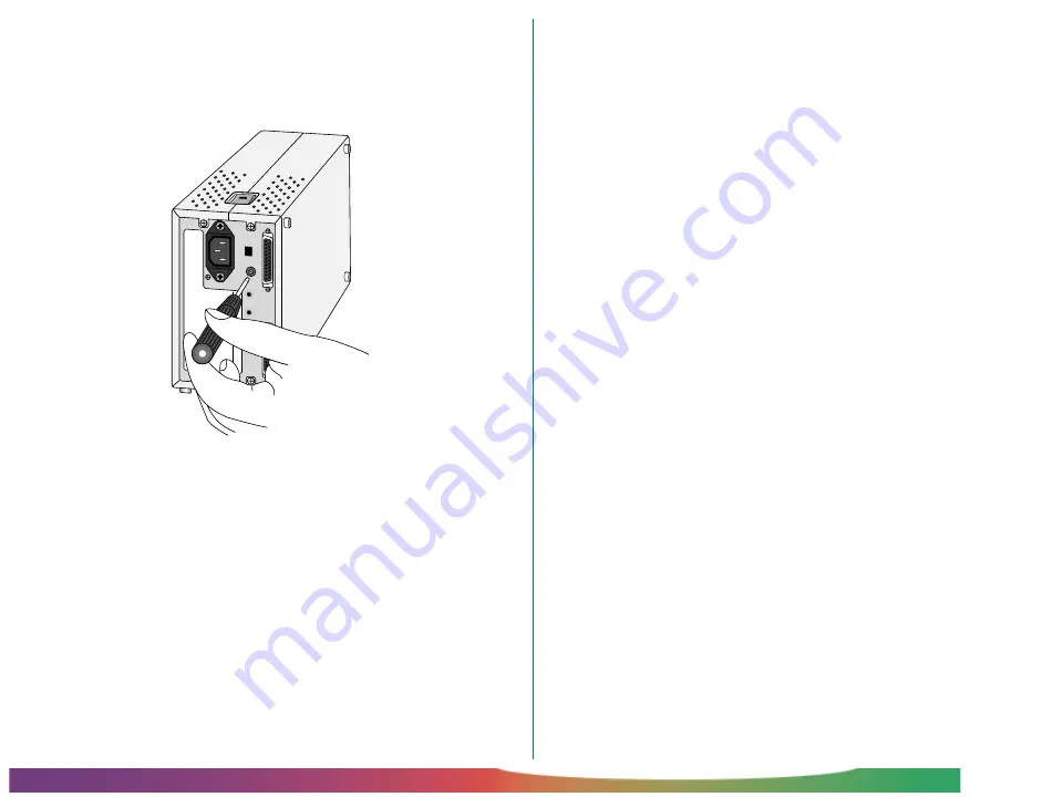
Setup:  Setting the SCSI ID

To change the scanner’s ID, turn the scanner off.  Then, using a
screwdriver, turn the dial on the back of the scanner to choose
a new ID.

MADE IN JAPAN

100098

SCSI

SCSI

SCSI NB

TERMINATOR

OFF

ON

6

5

4

3

2

1

0

7

Note:

  The LS-2000 conforms to Level 1 of the SCAM (SCSI

Configuration Auto-Magically) SCSI-selection standard, which allows
some computers to set the scanner’s ID automatically.  If your
computer’s operating system supports Plug&Play and the SCSI host
(computer or SCSI extension board) conforms to SCAM, the scan-
ner may be automatically assigned an ID which differs from that
set using the SCSI ID dial.  SCAM will not assign conflicting IDs to
SCSI devices.

Содержание LS-2000

Страница 1: ...ional Accessories System Requirements Parts of the LS 2000 Status LED Setup Installation Connecting the Power Cable Connecting the SCSI Cable Setting the SCSI ID Using the Scanner Turning the Scanner On Inserting and Removing Adapters Using the MA 20 SLIDE MOUNT ADAPTER Using the SA 20 STRIP FILM ADAPTER Using the IX240 Film Adapter IA 20 Using the SF 200 Slide Feeder Turning the Scanner Off ...

Страница 2: ... 2 Contents Maintenance Cleaning Storage Transport Troubleshooting Specifications ...

Страница 3: ...Corporation i386 i486 Pentium and Pentium II are trademarks of Intel Corporation U S A Adaptec is a registered trademark of Adaptec Inc Adobe and Acrobat are registered trademarks of Adobe Systems Inc The Defect Correction function incorporated in the LS 2000 makes use of Digital ICE technology developed by Applied Science Fiction Inc Digital ICE and the Digital ICE logo are trademarks of Applied ...

Страница 4: ... the equipment into an outlet on a circuit different from that to which the receiver is connected Consult the dealer or an experienced radio television techni cian for help CAUTIONS Modifications The FCC requires the user to be notified that any changes or modifications made to this device that are not expressly ap proved by Nikon Corporation may void the user s authority to operate the equipment ...

Страница 5: ...n which it is used which has a plug rated for AC 250V 15A NEMA 6P 15 and insulation of SVT type or better and which is more than AWG18 in thickness At voltages of AC 125V or less use a power cord that complies with the safety standards of the country in which it is used which has a plug rated for AC 125V 10A and insulation of SVT type or better and which is more than AWG18 in thickness Connect the...

Страница 6: ... or modify the power or SCSI cables Fire or electric shock may result if the cables are placed under heavy objects exposed to heat or flame or forcibly tugged or bent Should the insulation of the cables become damaged and the wires become exposed contact your retailer or Nikon service office for information on repair or replacement Continued use could cause fire or electric shock Do not plug the p...

Страница 7: ...g so could cause fire or electric shock Do not place heavy objects on the scanner Place on a stable surface Do not use the equipment on an unstable surface or on a surface which is not horizontal This could cause the equip ment to fall resulting in injury Do not drop Do not subject the equipment to strong shocks as this could cause malfunction or breakage The scanner contains glass parts if the sc...

Страница 8: ...ug the power cord and contact your dealer or nearest Nikon service office Continued use could result in fire electric shock or malfunction Particular care is advised in house holds with small children When not using for an extended period When not using the equipment for an extended period remove any film that may be in the adapters and take the adapters out of the adapter slot Turn off the equipm...

Страница 9: ... or storing the scanner When not in use cover the scanner appropriately to protect it from dust Do not store or use where the temperature is above 35 C 95 F or below 10 C 50 F the temperature changes drastically or condensation occurs the humidity exceeds 80 the scanner would be exposed to direct sunlight there is a lot of dust ...

Страница 10: ...al shock Note that the scanner contains glass parts if the scanner is dropped or otherwise damaged caution must be observed to avoid broken glass the scanner would be exposed to radio interference from other equipment nearby close to other objects that would block the scanner s vents ...

Страница 11: ...d The copying or reproduction of stamps issued by the gov ernment and certified documents stipulated by law is prohib ited Cautions on certain copies and reproductions The government has issued cautions on copies or reproduc tions of securities issued by private companies shares bills checks gift certificates etc commuter passes or coupon tickets except when a minimum of necessary copies are to be...

Страница 12: ... removing the film from the scanner continuous scanning of mounted slides with the SF 200 slide feeder sold separately This reference manual describes the procedures for unpacking setting up and connecting the scanner and explains how to use the film adapters available for the LS 2000 While the emphasis in this manual is on setting up and using the scanner the pre cautions that should be observed ...

Страница 13: ...er cable 1 Shape of cable depends on country of sale Scanner software CD ROM for Windows and Macintosh 1 Reference CD containing manuals and Adobe Acrobat Reader 1 User s guide 1 Open me first envelope 1 Fast Track guide 1 LS 2000 main unit 1 MA 20 SLIDE MOUNT ADAPTER 1 SA 20 STRIP FILM ADAPTER 1 FH 2 strip film holder for MA 20 1 Note Users in the United States and Canada should also find that th...

Страница 14: ... more is recommended video system supporting a color depth of at least sixteen bits or 32 000 colors a color depth of twenty four bits or 16 7 million colors is recommended Windows IBM PC AT or compatible with i486 or better CPU Windows 95 Windows NT4 0 or later a minimum of 16 MB free RAM 24 MB or more is recom mended 23 MB or more free hard disk space 100 MB or more is recommended DOS ASPI compa...

Страница 15: ...N 6 5 4 3 2 1 0 7 100 240V 0 3 0 2A 50 60 Hz AC connector Termination on off switch SCSI ID selection switch Holders for locking screws Female half pitch 50 pin SCSI connectors 2 Transport locking screw Status LED Feet used when scanner is on its side Transport locking screw Sliding cover Adapter slot Feet used when scanner is on its base Guard ...

Страница 16: ...lizing after having been turned on Do not turn the scanner off remove or insert adapters or eject or insert film When the status LED flashes rapidly ERROR a communications error has occurred or there is a problem with the scanner If this condition persists close all applica tions and turn off the computer then turn off the scanner Wait at least five seconds before turning the scanner on again and ...

Страница 17: ...ps are described in the sections that follow Installation Before connecting the LS 2000 to your computer choose a flat stable location for it free from vibration and dust Do not install your scanner where it would be exposed to direct or reflected sunlight it would be subject to condensa tion or drastic changes in tempera ture the temperature exceeds 35ºC 95ºF or falls below 10ºC 50ºF other object...

Страница 18: ... should be at least 5 cm 2 of space above the unit or 15 cm 6 when the optional SF 200 slide feeder is in place Leave 10 cm 4 of space behind the unit Space requirements are illustrated below When installing the scanner on its base When installing the scanner on its side Caution The scanner must be installed with its feet down as shown in the illustrations on this page Do not store or operate the ...

Страница 19: ...moved After removing the transport screw from the adapter slot and screwing it into one of the holes on the rear of the scanner remove the guard and store it in a safe place Caution Never turn the scanner on with the locking screws in place Turning the power on in these circumstances could damage the scanner Note Replace the locking screws and guard when transporting the scanner see Maintenance Tr...

Страница 20: ...ly could result in electric shock The scanner and all devices to which it is connected must be connected to a common ground If a common ground is not used a ground loop could occur causing electric shock or static noise Do not plug the power cord into an extension cord or multiple outlet extension as this could result in fire or malfunction Use an independent outlet whenever possible If the scanne...

Страница 21: ...ter is powered on after installation the Windows Hardware Wizard should detect the SCSI adapter and if necessary prompt you to install driver software for the device Once installation is complete check to be sure that the system resources used by the adapter do not conflict with those used by other devices If any conflicts are found resolve them as instructed in the manufacturer s manual Caution D...

Страница 22: ...osh laptop computers use a different type of connector SCSI boards for IBM PC AT computers will usually be provided with a 25 pin D sub connector a 50 pin Centronics connector or a half pitch 50 pin connector with the pins ar ranged in two separate rows or attached to a central finger If the correct type of cable is not available an adapter can be attached to one or both ends of the cable To preve...

Страница 23: ...er MADE IN JAPAN 1 0 0 0 9 8 S C S I S C S I SCSI NB TERMINATOR OFF ON 6 5 4 3 2 1 0 7 Connect the other end of the cable to the next device in the chain If the scanner is the only external device in the chain connect the cable to the computer s SCSI port MADE IN JAPAN 1 0 0 0 9 8 S C S I S C S I SCSI NB TERMINATOR OFF ON 6 5 4 3 2 1 0 7 100 240V 0 3 0 2A 50 60 Hz If there are other external devic...

Страница 24: ... separate terminator should be attached to it even if the device is connected to the SCSI chain using a through terminator When the scanner is between other devices Set the terminator switch on the rear of the scanner to OFF TERMINATOR OFF ON Connect one end of the SCSI cable to either of the connectors on the rear of the scanner then connect the other end to one of the devices in the chain MADE I...

Страница 25: ...d If you experience trouble with SCSI connections contact the manufacturer to learn whether an updated driver has been released Setting the SCSI ID Each device in the SCSI chain has a unique ID which is a num ber between zero and seven that the computer uses to distin guish between different devices When connecting the LS 2000 to a SCSI chain the scanner s SCSI ID must be set to a number that is n...

Страница 26: ...Note The LS 2000 conforms to Level 1 of the SCAM SCSI Configuration Auto Magically SCSI selection standard which allows some computers to set the scanner s ID automatically If your computer s operating system supports Plug Play and the SCSI host computer or SCSI extension board conforms to SCAM the scan ner may be automatically assigned an ID which differs from that set using the SCSI ID dial SCAM...

Страница 27: ... other peripheral devices and then start the computer Inserting and Removing Adapters The LS 2000 uses a variety of adapters to scan different types of film Adapters are provided for scanning single 35 mm slide mounts and 35 mm film in strips of from two to six frames Other adapters are available separately for scanning IX240 film and for consecutive scanning of 35 mm slides All of these adapters ...

Страница 28: ... Using the MA 20 SLIDE MOUNT ADAPTER When scanning 35 mm slides insert the slide adapter into the scanner stopping when the adapter is firmly in place The adapter should be oriented relative to the scanner as shown in the illustration below Inserting slides Film has an emulsion surface and a base when examined under a light the emulsion side is dull and the base shiny Looked at from the base side ...

Страница 29: ...opping when it contacts the back of the slot If the scanner is installed on its base the shiny surface of the film should face to the left and the emulsion surface to the right The correct orientations for inserting landscape and portrait slides are shown below If the slides are inserted with the top and bottom of the image reversed this can be corrected after scanning using the software provided ...

Страница 30: ... the longer side of the aperture facing the scanner The scanner will be unable to scan the edges of the film Note The best possible results can be achieved only with clean slides Before scanning remove dust from the film with a blower and wipe the slide gently with a soft dry cloth to remove finger prints ...

Страница 31: ...out with your fingers Cautions Do not attempt to insert or eject slides while scanning is in progress Do not move the scanner or subject it to shock or vibration while scanning is in progress Slides must be between 1 0 mm and 3 2 mm in thickness If the surface of the mount is rough you may experience some resistance when inserting or removing the slide Do not leave slides in the adapter for extend...

Страница 32: ...APTER following Film that cannot be scanned using the SA 20 can be scanned in the MA 20 using the FH 2 strip film holder provided with your scanner This section details how to insert film in the FH 2 and scan it using the MA 20 Step 1 Open the FH 2 Holding the FH 2 with the Nikon logo facing upwards unlatch the holder by the snaps and flip it open Step 2 Place film in the holder Place a strip of 3...

Страница 33: ...scanned with one of the two apertures in the metal part of the FH 2 Step 5 Insert the FH 2 into the slide adapter Insert the FH 2 in the film slot of the MA 20 with the Nikon logo upwards The direction of insertion depends on which of the frames in the apertures of the metal part of the FH 2 is to be scanned in the illustrations below the arrows show the direction of insertion 1 4 The first frame ...

Страница 34: ...lows steadily then slide the holder out by hand Do not use the eject button Cautions If the holder does not slide smoothly into the adapter film slot remove it from the adapter and try again Do not use force The film holder is for use with the MA 20 only Do not attempt to use the holder with other adapters Before scanning remove dust from the film with a blower or brush Do not use the eject button...

Страница 35: ...it con tacts the back of the slot Push the adapter until the connector on the rear of the adapter is seated securely in the socket at the back of the slot A plastic tray is provided with the strip film adapter to catch film ejected from the scanner If the scanner has been installed on its side this tray can be attached to the adapter by inserting the hooks on the back of the tray into the holes pr...

Страница 36: ...or fail to scan properly Film for use in the scanner should fit in the gauge on top of the adapter 3 mm Film will be ejected from the scanner automatically when the scanner is turned on or when no operation is performed for several minutes Film can also be ejected using the software provided with your scanner For details of scanning operations refer to the User s Guide or software reference manual...

Страница 37: ... finger prints If there is dirt on the film damage to the film could result Before scanning remove dust with a blower and gently wipe off any finger prints with a soft dry cloth What to do if film jams in the adapter If film cannot be ejected from the scanner using the software provided or does not eject automatically after ten minutes have passed with no operation being performed you will need to...

Страница 38: ...e free end with the other being sure that the film does not catch on the adapter or other objects Keep the angle at which film is pulled from the adapter as low as possible to prevent damage to the film Step 4 Close the adapter Close the adapter and with a coin or screwdriver tighten the screw on the top of the adapter until the top portion of the adapter is securely in place When film protrudes f...

Страница 39: ...f the adapter Open the adapter and remove all dust with a blower When you have finished close the adapter and with a coin or screwdriver tighten the screw on the top of the adapter until the top por tion of the adapter is securely in place Using the IX240 Film Adapter IA 20 An optional adapter for scanning IX240 film with the LS 2000 is available for separate purchase To use the IX240 adapter inse...

Страница 40: ...to open the adapter cover Insert the film cartridge in the film chamber as shown below Close the cover pushing it closed until the latch snaps into place The scanner will automatically feed film from the IX240 cartridge into the scanner For details on scanning IX240 film see the software reference manual Note If no operation is performed for several minutes the film will automatically be wound bac...

Страница 41: ...images in a session as possible to minimize the number of times the film is wound and unwound If you notice an unusual noise when scanning IX240 film remove the film as described below and take it to a developer to have a copy made Use the copy when making further scans Removing Film To remove film from the adapter click the eject button in the Nikon Scan scan window see the software reference man...

Страница 42: ...urely in the socket at the back of the slot The SF 200 is properly inserted if the status LED on the front of the feeder lights when the scanner is turned on If the scanner is on when the SF 200 is inserted the feeder s status LED will blink once to indicate that the feeder has been inserted cor rectly In all other respects the feeder LED functions in the same way as the scanner status LED Caution...

Страница 43: ...ges in the slides should be reversed when viewed from the magazine side Scanning will be considerably simplified if the slides are all inserted in the same orientation Slides can be loaded into the feed magazine up to the load mark Do not attempt to fill the magazine past this point Once the feed magazine is loaded release the push plate from the notch and slide it back until rests against the sli...

Страница 44: ...longer side of the aperture facing the scanner as this could damage the film or slide mount or cause the feeder to jam Insert slides as shown by the insertion guide sticker next to the feed maga zine see illustration on page 43 Do not load slides in the feed magazine past the load mark as this may cause the feeder to jam Do not move the scanner while scanning is in progress Remove scanned slides f...

Страница 45: ...are that came with your scanner is required both when attaching this part to and removing it from the feed mechanism To attach the feed mechanism attachment both your scanner and computer must be on After inserting the SF 200 into the scanner as described above open the Utility folder in the folder to which you installed Nikon Scan and then double click the Attachment Utility icon to start the att...

Страница 46: ... will need to remove the attachment Use the attach ment utility as described above to move the feed mechanism into the magazine then remove the attachment and click OK to return the feed mechanism to its initial position What to do if the feeder jams If a jam occurs open the magazine cover and remove the slides remaining in the feed and eject magazines Pull back the feed push plate and hook it in ...

Страница 47: ...ing a slide click the double left arrow button in the attachment utility window to move the feed mechanism back to its housing then remove the jammed slide with your fingers If two or more slides have jammed so that they overlap remove the slide on the magazine side first If the mount has caught at the entrance to the ejec tion magazine while being ejected from the feeder click the right arrow but...

Страница 48: ...ff the computer Wait for until the status LED is glowing steadily then turn the scanner off Cautions Be sure that the computer is off before turning off the scanner and other peripherals Do not turn the scanner off while the status LED is blinking Once the power is off wait at least 5 seconds before turning the scanner on again ...

Страница 49: ... liquids come in contact with the interior of the scanner fire electric shock or malfunction could result Volatile liquids such as alcohol benzine or thinner could stain the exterior of the scanner and adapters Periodically unplug the power and SCSI cables and wipe the dust off with a damp cloth Do not allow dust to collect on the plug as this could cause fire Storage When you do not plan to use t...

Страница 50: ... status LED glows steadily then turn off and unplug the scanner Place the guard in the adapter slot as shown below sliding it in until it contacts the back of the slot Remove the transport locking screws from the rear panel and screw them into the holes provided in the side panel and the mouth of the adapter slot the hole in the mouth of the slot should align with the hole in the guard Close the f...

Страница 51: ...SI chain terminated If the SCSI chain is not properly terminated you will experi ence intermittent problems with all SCSI devices The chain must be terminated at both ends if you have a IBM PC AT compatible with a SCSI expansion board and no internal SCSI devices check that the board is terminated refer to the manufacturer s manual If you are using an IBM PC AT compatible with a SCSI expansion boa...

Страница 52: ...er system satisfy the requirements given in Parts and Accessories in this manual and in the User s Guide Is the software installed correctly Installation instructions are given in the Fast Track Guide and the software reference manual As a last resort it may be necessary to reinstall the scanner software Follow the instructions for de installation given in the software reference manual for your pl...

Страница 53: ...s the scanner on Is the slide feeder properly connected to the scanner After confirming that scanning is not in progress remove and reinsert the adapter as described in Using the Scanner in this manual Problem the quality of scanned images is poor Checklist Is there dust on the film Remove dust from the film with a blower and scan the image again Is the film to be scanned properly inserted in the ...

Страница 54: ...x 35 4 mm Pixel size Square 9 4 µm x 9 4 µm pixels Optical resolution Maximum 2700 pixels 25 4 mm or 2700 dpi at film surface Analog to digital conversion 12 bits for each color Output Full color 8 or 12 bits for each color Focus Autofocus Interface SCSI 2 compliant half pitch 50 pin connec tors x 2 Dimensions 85 5 mm W x 275 0 mm D x 142 0 mm H 3 37 10 83 5 59 Weight Approx 2 4 kg 5 lbs 5 7 oz Po...

Страница 55: ...ode Connected directly to the connector at rear of scanner adapter slot Dimensions 84 0 mm W 207 5 mm D 58 5 mm H 3 31 8 17 3 30 Weight Approx 270 g 9 6 oz Power supply 5 VDC 1 7 A or less supplied from LS 2000 SF 200 slide feeder option Film 35 mm slide mount of 1 0 mm to 3 2 mm in thickness Maximum number of slides Approx 50 slides with mounts 1 5 mm in thickness Housing space Approx 78 5 mm Ope...

Страница 56: ...NORMENGERECHTHEIT Wir Name Nikon Europe BV Anschrift Schipholweg 321 1171 PL Badhoevedorp The Netherlands erklären hiermit daß das folgende Produkt Produktbezeichnung Nikon Film Scanner LS 2000 SLIDE MOUNT ADAPTER MA 20 STRIP FILM ADAPTER SA 20 IX240 Film Adapter IA 20 Slide Feeder SF 200 Name des Herstellers Nikon Corporation Anschrift des Herstellers Fuji Bldg 2 3 Marunouchi 3 chome Chiyoda ku T...

Отзывы: