


SD Series
Operating & Safety Instructions
USA 10/12
19
4
Operation
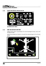
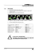
4.1
CONTROL CIRCUIT COMPONENTS
4.1.1
CONTROL BOARD: -
Situated behind the door, the encapsulated control board comprises of a PCB
(printed circuit board) design which incorporates all of the relays to control the machine operation. The
control board is common to all models and contains functions which might not be utilised on your
machine. Thermal trip switches are integral to the box, which protect the control circuit components. If
power is lost, the switches can be manually reset.
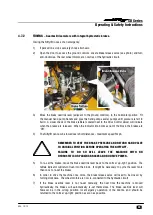
4.1.2
TILT ALARM: -
Fitted to the base of the machine, the tilt alarm is a solid state sensor which monitors
the inclination of the machine. When the booms are raised, the angle of inclination is monitored, giving
an alarm if the maximum angle is exceeded on set-up. The tilt alarm does not operate when the
machine is being driven, as the boom switch overrides this function as long as the booms are lowered.
4.1.3
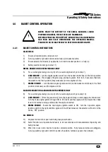
SOUNDER: -
Situated adjacent to the PCB is a small electric sounder, which is used to provide an
intermittent alarm whenever the machine is in operation. Pushing a green “power control” button or
depressing the foot switch in the basket (if fitted) will energise this sounder. This serves to warn
personnel of the operation of the machine.
4.1.4
KLAXON: -
Also mounted next to the engine key switch is a klaxon, which performs several functions.-
Firstly, it can be used as a manual alert, by pushing the “Horn” button at the Basket Control Station.
Secondly, it is the device which sounds continuously if the tilt alarm sensor detects excessive
inclination, with the booms raised.
Lastly, it is linked into the battery management system, such that when low battery state is reached the
“pulsing” of the DC motors is mimicked by the Klaxon, re-enforcing the message to the operator to re-
charge the batteries.
4.1.5
DRIVE CONTROL VALVE (DCV):-
The motion control valve comprises of several individual
components all directly involved in the hydraulic supply to the wheel drive motors. The pressure relief
valves and non-return valves serve to control the machine speed in normal drive and to prevent over-
speed when descending slopes.
4.1.6
BRAKE RELEASE VALVE (BRV):-
The motion control valve also incorporates a solenoid operated
dump valve which controls the brake function on the machine. This valve must be energised to allow
the machine to move. If no voltage is present, the wheel motors will not be able to develop drive
torque, whilst at the same time, the hydrostatically applied parking brakes will remain engaged. Only
when the green “power control” button is being used (or the basket foot switch is depressed) will the
BRV operate. Pressing the drive joystick trigger will then energise the BRV and permit the drive
function.
4.1.7
BOOM SWITCH: -
Mounted between the main booms, near the knuckle and operated by a cam, this
switch controls both the operation of the tilt alarm sensor, and the outrigger interlock. With the booms
in the stowed position, the tilt alarm sensor is bypassed, allowing the machine to negotiate slopes in
excess of the permissible working angle, without isolating the drive function. At the same time, fast
throttle is enabled. When the booms are raised, the tilt alarm sensor becomes activated, and the boom
switch isolates the jack control circuit. These control functions are of primary importance to the safety
of the machine and operator; under no circumstances should this control function be isolated or
bypassed.