


Installation
5
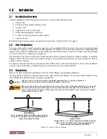
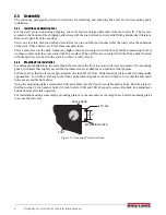
2.5
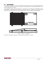
Junction Box Connections
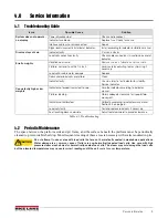
The indicator terminal strip is used to connect the main cable to the indicator which is shown in Figure 2-3
Determine the indicator’s load cell input connections from the operating manual. Run a cable from your indicator
terminal into the junction box and make the connections. The following table shows the correct junction box
connections using the cable color code.
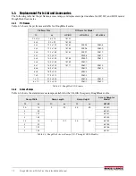
Table 2-1. Junction Box Connections
Cable Color Code
Junction Box
Red
+ Excitation
Black
- Excitation
Green
+ Signal
White
- Signal
Brown
Shield
Yellow
+ Sense
Blue
- Sense
JP4
JP 2
PT4
PT3
JP3
PT1
EXP
PT2
JP1
1
CELL4
1
CELL1
1
CELL3
1
CELL2
IND
-EX
-SI
SHD
+SI
+EX
M
R
N
I
-SI
S2C
I
A
G
+EX
+SI
-SI
SHD
-EX
I
S
G
A
L
T
+SI
M
S
I
N
L
T
R
+EX
-EX
-SI
SHD
+SI
+EX
+SI
-EX
-SI
SHD
-EX
SHD
+SE
-SE
+EX
Figure 2-3. Junction Box Indicator Terminal
2.5.1
Electrical Interface to Indicator
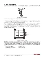
Twenty feet of 6-wire cable to connect the scale to the weight indicator is supplied with each scale. The cable must
be routed to the indicator in a manner that will protect the cable from damage. Two methods of cable protection in
non-washdown applications are shown. When planning cable routing with either of these two methods, leave a
loose coil of excess cable under the scale to facilitate future lifting of the scale for servicing or cleaning.
LOAD CELL CABLE
STEEL COVER
FLOOR
SCREW
LOAD CELL CABLE
STEEL COVER
Figure 2-4. Electrical Interface to Indicator
When the interface cable is protected and in its final position, complete connections to the indicator. See indicator
installation manual for wiring information.
Содержание RoughDeck
Страница 2: ...RoughDeck Low Profile Floor Scale HP HP H HC and ROUGH N READY Installation Manual PN 66662 Rev F...
Страница 3: ......
Страница 20: ......


