Nice ALTO100C Скачать руководство пользователя страница 28

27

 – English

English

% /LVWRIPRGLƄDEOHSDUDPHWHUV7DEOH

• Pause time

: this is the time implemented by the control unit after an 

opening manoeuvre before automatically closing the leafs. 

Warning

 – 

the pause will only be enabled if the “complete cycle” option is pro-
grammed (i.e. automatic re-closing of the gate) during programming as 
described in paragraph 7.3.2.

• “Pedestrian” command

: comprises 4 types of command related to 

the leaf “partial open”. During use of the automation the set command 
is activated when the key T2 is pressed on the transmitter.

• Motor force

: normally, during a manoeuvre the motor implements a 

RODBHjBENQBDSNLNUDSGDKD@ESNBNLODMR@SDENQHSRVDHFGSEQHBSHNMNM

the hinge pins and any presence of wind etc.

  During a manoeuvre, if an inadvertent obstacle brakes the leaf further, 

the motor increases the force applied in the attempt to overcome the 
obstacle. At this point, if the force generated by the obstacle causes 
the motor to exceed the set level, the control unit immediately activates 
a safety manoeuvre, inverting movement of the leaf. Therefore, if the 
parameter is suitably set, this guarantees increased safety.

•  “Step-by-Step” command

: comprises 4 types of “step-step” com-

mand, i.e. a command in which each press of the key activates the sub-
sequent manoeuvre after the one completed or in progress, according to 
the pre-set order in the set sequence. During use of the automation, the 
set command is activated when the transmitter key T1 is pressed and on 
the devices connected to the control unit by means of the terminal “SbS”.

• Pressure discharge

: this parameter, when suitably set, enables dis-

charge of the pressure applied on the structure when the leafs are sta-
tionary and positioned against the opening or closing travel limit stops.

All parameters can be set as required, with the exception of the param-
eters “Motor force” and “Pressure discharge” which must comply with the 
following requirements:

Motor force:

• Never use excessively high force values to compensate for any abnor-

mal gate movements caused, for example, by points of increased fric-
tion. In fact, excessive force may impair correct operation of the safety 
system or damage the leaf.

• If the “Motor force control” is used in support of the system for impact 

force reduction, after each adjustment the force measurement proce-
dure must be performed, as envisaged by standard EN 12445.

•  The local weather conditions (for example, strong gusts of wind) can 

HMkTDMBDKD@ELNUDLDMSB@TRHMF@MHMBQD@RDHMSGDKN@C@OOKHDCNM

the motor. Therefore the “Motor force” parameter may require periodic 
adjustments”.

Pressure discharge:

• Never use excessively low pressure discharge values as these would 

have no effect; they may also cause damage to the leaf and the travel 
limit stop.

• Never use excessively high pressure discharge values as these would 

keep the leaf separate from the travel limit stop.

• Use a pressure discharge value that enables the leaf to remain in con-

tact with the travel limit stop, without this applying excessive pressure 
on the motor.

B.3 -  Checking parameter settings

The settings of a required parameter can be checked at any time accord-
ing to the procedure below.

01.

 In 

Table 9

 select the parameter to be checked (the meanings of the 

parameters are explained in paragraph B.2).

02.

 On the transmitter, press and hold keys T1 and T2 or T1 and T3 

simultaneously (see 

Table 9

) for at least 5 seconds; then release the 

keys.

03.

 (within 3 seconds) On the transmitter, press and hold the key of the 

O@Q@LDSDQSNADBGDBJDC@MCQDKD@RDVGDMSGDk@RGHMFKHFGSRS@QSRSN
k@RG

 "NTMSSGDMTLADQNEk@RGDR@MCBNMRTKS

Table 10

 (column “N.”) to 

locate the same number; read the currently set value of the parameter 
being checked alongside. 

Example

LIWKHƅDVKLQJOLJKWHPLWVƅDVK

-

HVWKLVPHDQVWKDWWKHqSDXVHWLPHrLVSURJUDPPHGDWVHFRQGV

C - MEMORISING OR DELETING RADIO 

TRANSMITTERS

C.1 -  Memorising the FIRST transmitter

The transmitters supplied are not memorised;  therefore, at the beginning, 
it is necessary to memorise the FIRST transmitter (Mode 1), with the pro-
cedure C.2.

C.2 -  “Mode I” memorisation procedure

When this procedure is used, the system automatically associates each 
transmitter key with the following commands:

key 

T1

 = 

“Step-by-Step” 

command (> Open > Stop > Close > ...)

key 

T2

 = 

“Pedestrian”

 command (> Total opening of 1 leaf > ...)

key 

T3

 = command 

> Open > Stop > ...

key 

7

 = command 

> Close > Stop > ...

Notes:


• 

7KH7NH\LVQRWXVHGLQWKLVDSSOL

-

cation. 

s7KHFRPPDQGVRIWKH7DQG7NH\V

FDQEHPRGLƄHGE\WKHXVHUVHHSDUDJUDSK%
DQG7DEOHs7KHV\PEROq!rPHDQVqSUHVV

the key once”.

Therefore to memorise these commands simul-
taneously on the 4 keys of a transmitter, pro-
ceed as follows.

01.

 On the control unit, press and hold P1 on the receiver until the green 

Led P1 illuminates, and then release.

02.

  (within 10 s) press any key on the transmitter for at least 2 s to memo-

rise it.


If the memorisation procedure is successful, the LED P1 will emit 3 

k@RGDR

03.

 If there are other transmitters to be memorised, repeat phase 02 

within the next 10 seconds; otherwise the memorisation procedure 
terminates automatically.

A transmitter memorised in Mode I can control 1 automation only, using 
the 4 commands.

C.3 -  “Mode II” memorisation procedure

When this procedure is used, it is the installer’s task to associate the 
transmitter key with the required command, from those available. There-
fore, to memorise a command on a key, proceed as follows. Therefore, to 
memorise a command on a key, proceed as follows.

01.

 Refer to the table below; choose the command to be memorised 

and note the number of times the transmitter needs to be pressed (in 
phase 03) to memorise it.

 • 

“Step-by-Step” command (

> Open > Stop > Close > ...

press once

 • 

“Pedestrian” command (

> Total opening of 1 leaf > ...

)


press twice

 • 

command 

> Open > Stop > ...


press three times

 • 

command 

> Close > Stop > ...


press four times


Notes:


s7KHFRPPDQGVq6WHSE\6WHSrDQGq3HGHVWULDQrFDQEH

PRGLƄHGE\WKHXVHUVHHSDUDJUDSK%s7KHV\PEROq!rPHDQV

“press the key once”.

02.

 On the control unit, press P1 for the same number of times as the 

command to be memorised and ensure that Led P1 emits a number 

NEPTHBJk@RGDRBNQQDRONMCHMFSNSGDMTLADQNESGDRDKDBSDCBNL

-

mand.

03.

 (within 10 seconds) press the required key of the transmitter to be 

memorised for at least 3 seconds. If memorisation is successful, Led 

/NMSGDBNMSQNKTMHSVHKKDLHSRKNVk@RGDR

 If there are other transmitters to be memorised for the same type of 

command, repeat step 03 within the next 10 s otherwise the memori-
sation phase will end automatically.

To


memorise another key, repeat the procedure from the beginning.

C.4 -  Duplicating an existing and previously memo-

rised transmitter

This procedure enables memorisation on the control unit of a new trans-
mitter, by duplicating the characteristics of another existing and previously 
memorised transmitter. During this procedure, take care to observe the 
following warnings:
– if the transmitter to be duplicated is memorised in Mode I, when the 
request to press a button is made, any key on the two transmitters can 
be pressed;
– otherwise, if the transmitter to be duplicated in memorised in Mode II, 
when the request to press a button is made, the key with the command 
to be duplicated must be pressed on the “old” transmitter, followed by the 
key to be associated with this command on the “new” transmitter.

01.

 Ensure that the two transmitters are located within the reception 

range of the automation and press the key on the “new” radio trans-
mitter for at least 5 seconds, then release.

02.

  Press the key on the OLD radio transmitter slowly 3 times.

03.

  Press the key on the NEW radio transmitter slowly once.
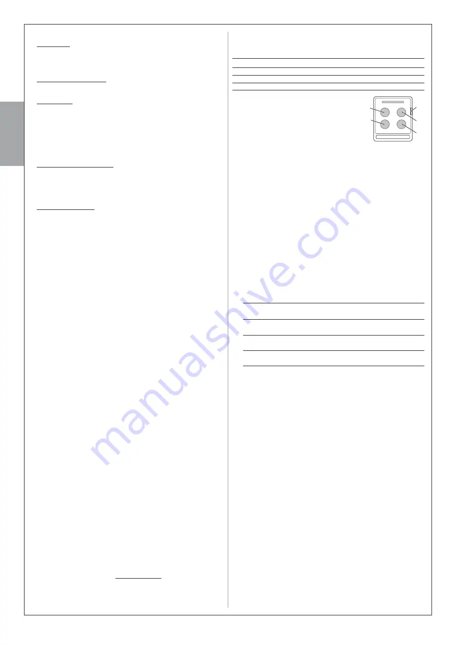
T4

T2

T5

T3

T1

Содержание ALTO100C

Страница 1: ...GATE AUTOMATION ALTO Instructions and warnings for installation and use ...

Страница 2: ...dvertent resetting of the thermal cut off device this appliance must not be powered through an ex ternal switching device such as a timer or connected to a supply that is regularly powered or switched off by the circuit Provide a disconnection device not supplied in the plant s mains pow er supply with a contact opening distance that ensures complete dis connection under the conditions envisaged b...

Страница 3: ...l unit to enable a number of emergency manoeuvres following a power failure black out During the power failure or at any other time the gate KD ER B M AD LNUDC L MT KKX HE QDPTHQDC AX jQRS QDKD RHMF SGD FD QLNSNQ using the relative key 2 2 DEVICES AND ACCESSORIES REQUIRED TO SET UP A COMPLETE SYSTEM Fig 1 illustrates all devices and accessories required to set up a complete system such as that sho...

Страница 4: ...e gate can be auto mated using standard length arms supplied as standard if the point is located within area C this product cannot be used to automate the gate 2 Maximum leaf height The ALTO system can automate leafs with a height of up to 200 cm 3 Maximum leaf width The ALTO system can automate leafs with a width of up to 160 cm see Graph 1 Maximum leaf weight The maximum weight of the leaf depen...

Страница 5: ...XFW UDQJH When selecting the position of each device take special care to observe the following Gearmotors the gearmotor with control unit must be positioned on SGD KD E BKNRDRS SN SGD YNMD VGDQD SGD ONVDQ RTOOKX HR KNB SDC PH200 photocells the two photocells TX and RX must be posi tioned a at a height of 40 60 cm from the ground b to the sides of the YNMD SN AD OQNSDBSDC c outside the gate i e on...

Страница 6: ...unit cable 3 x 1 mm 10 m Note 1 WHUQDO FDEOH GLDPHWHU 0D LPXP PP Note 2 I WKH SRZHU FDEOH LV ORQJHU WKDQ P D FDEOH ZLWK D ODUJHU VHFWLRQ LV UHTXLUHG H J PP DQG VDIHW HDUWKLQJ LV QHFHVVDU LQ WKH YLFLQLW RI WKH DXWRPDWLRQ Note 3 RU WKHVH FRQQHFWLRQV D VLQJOH FDEOH ZLWK PXOWLSOH LQWHUQDO ZLUHV PD EH XVHG 7KLV HQDEOHV JURXSLQJ RI PXOWLSOH FRQQHFWLRQV IRU H DPSOH WKH 6723 DQG 6E6 LQSXWV FDQ EH FRQQHFWH...

Страница 7: ...mponents making up the gearmotor arm a Refer to ƄJ but without insert HMF SGD RSNO ADMYHMF ƄJ this will be inserted later Caution ONRHSHNM SGD DKANV jSSHMF NE SGD arm so that is curved towards the leaf of the gate ƄJ when the gearmotor is installed 02 Establishing the height from the ground of the gearmotor when installed on the post a Place the gearmotor on the post and position it so that the br...

Страница 8: ...the minimum possible value This will be the required value A e On the post note the selected value A and trace a vertical line from this point ƄJ 3GD KHMD LTRS HMSDQRDBS SGD GNQHYNMS K KHMD KQD CX OQDRDMS SGDRD SVN KHMDR VHKK RDQUD R QDEDQDMBD ENQ RTARDPTDMS jW ture of the gearmotor f Lastly release the gearmotor with reference to the chapter Manually locking and releasing the gearmotor in the Ope...

Страница 9: ...DC R CDRBQHADC below otherwise skip to phase 04 1 QDLNUD SGD RKNSSDC QL EQNL SGD jWHMF AQ BJDS NM SGD KD E 2 loosen the bracket screws and move it by a few millimetres in the direction of the gearmotor 3 QDjS SGD RKNSSDC QL NM SGD AQ BJDS BKNRD SGD KD E MC DMRTQD SG S it is aligned in contact with the travel stop and aligned with the other leaf if present Caution If necessary repeat point 2 to obt...

Страница 10: ...9 English English 1 2 3 45 3 1 2 a c b OK b a a b c d b a 5 6 7 8 9 10 11 12 13 13 ...

Страница 11: ...hrough to the leaf hinge pin If the string is found between the hinge pin and post in the area of the hinge pin posi tion BB in ƄJ extend the slotted arm by a few millimetres value C and repeat the check Repeat the procedure several times HE MDBDRR QX TMSHK SGD RSQHMF HR KNB SDC ADSVDDM SGD F SD SQ MRHS YNMD and the leaf hinge pin position AA in ƄJ and until the arm no KNMFDQ BNLDR HMSN BNMS BS VH...

Страница 12: ... the centre of the brackeS MC HMRDQS RBQDV DQL MDMSKX jW SGD AQ BJDS AX SHFGSDMHMF the three screws fully down c HW SGD RKNSSDC QL SN SGD AQ BJDS HMRDQSHMF SGD OHM MC RSNO ADMYHMF 10 Manually locking the gearmotor a Manually move the leaf to approximately mid travel and lock the gearmotor by means of the special key refer to chapter Manually locking and releasing the gearmotor in the Operation Man...

Страница 13: ...English 12 English OK b a 1 2 17 1 2 16 3 AA ok BB no OK 18 2 1 ...

Страница 14: ...13 English English b a 1 2 3 5 6 20 a b 1 2 3 19 ...

Страница 15: ... mm 360 a b a b 90 a b b c a 9 mm max c a b c 1 2 3 5 6 7 8 9 10 11 12 21 CAUTION If the length of the gate post is between 80 and 135 mm WKH UHDU JHDUPRWRU Ƅ LQJ EUDFNHW VKRXOG EH WXUQHG WKURXJK ref paragraphs 4 1A and 4 1B ...

Страница 16: ... 7 WUDQVPLWWHU WRZDUGV WKH FHQWUDO RQH RI WKH 5 UHFHLYHU DOORZHG PLVDOLJQPHQW PD LPXP 01 Remove the front glass Phase 01 Fig 02 Remove the upper casing then the internal casing of the photocell Phase 02 Fig 03 Perforate the lower casing in the point where the cables should pass Phase 03 Fig Position the lower casing in the point where the tube for the pas sage of the cables arrives and mark the pe...

Страница 17: ...English 16 English a b a b 1 2 3 5 6 7 8 9 10 11 23 ALTO100M gearmotor connection ref paragraph 5 1 ...

Страница 18: ...17 English English QVWDOODWLRQ DQG FRQQHFWLRQ RI ƅDVKLQJ OLJKW ref paragraph 5 2 Ø 6 mm x4 05 B Ø 6 mm x4 05 A 2 1 01 02 03 aerial flash 2 1 06 07 08 09 ...

Страница 19: ...tovoltaic power supply JA JB Led BUS Led SbS Led STOP Led P1 Led P2 Led P3 27 25 1 Led SAFE 3 2 4 Ø 5 mm 01 02 03 05 Installation and connection the pair of photocells PH200 ref paragraph 5 3 ALTO100C FL200 PH200 ALTO100M NC NO M M M M FLASH BUS STOP SbS ALTO100C ALTO100M FLASH 26 ...

Страница 20: ...l unit must be connected perma nently SN SGD DKDBSQHB K L HMR BQD SHMF RODBHjB ONVDQ KHMD VGHBG KRN includes a device to disconnect the automation from the power supply For these operations read paragraph 8 1 6 2 IDENTIFYING KEYS AND LEDS ON THE CONTROL UNIT From the next paragraph onwards the manual will deal with the keys leds and connectors present on the control unit To identify them refer to ...

Страница 21: ...AMETER SETTINGS 3URJUDPPLQJ WKH OHDI PRYHPHQW VSHHG The speed of the leaf during opening or closing may be set by selecting one of two options low speed or high speed 3N OQNFQ L SGD QDPTHQDC NOSHNM AQHDkX OQDRR MC BGDBJ SGD RS STR NE Led P2 if this turns off it means that the low speed option is set other wise if it turns on it means that the high speed option has been selected To switch between o...

Страница 22: ...DQ BNUDQ of the gearmotor 8 1 2 Installing the safety devices on the electrical line The automation power line must be equipped with a device for protection against short circuits and a device for disconnection of the automation from the power mains neither devices are supplied with the kit 3GD CHRBNMMDBS CDUHBD LTRS G UD BNMS BSR VHSG RTEjBHDMS F O SN DMRTQD complete disconnection in compliance w...

Страница 23: ...QCR STEP 10 MAINTENANCE AND DISPOSAL 10 1 PERIODIC MAINTENANCE Maintenance must be performed in strict observance of the safety provisions in this manual and according to current legislation and standards In general the devices in the ALTO system do not require special main tenance however periodic inspections will enable the user to maintain RXRSDL DEjBHDMBX MC DMRTQD BNQQDBS NODQ SHNM NE SGD R E...

Страница 24: ...f the arrow take care to avoid the wires below 02 Remove the connector with 5 wire plate C pulling it in the direction of the arrow 03 Lastly loosen the screws of the power terminal D and withdraw the 3 wires DXWLRQ KHQ WKH FRQQHFWRU ZLWK ZLUH SODWH LV UHƄWWHG WDNH FDUH WR REVHUYH SRODULW WKH FRQQHFWRU FDQ RQO EH ƄWWHG LQ RQH direction A 3 Replacing the power supply unit fuse 01 Access the power s...

Страница 25: ...ckup EDWWHU LI ƄWWHG 03 Connect the adaptor cable supplied with the kit SOLEKIT to the socket on the control unit taking care to observe polarity refer to the B AKD HMRSQTBSHNM KD kDS Caution the cable connector can only be inserted in one direction RSKX HMRDQS SGD BNMSQNK TMHS HM HSR RD S QDjS SGD B AKD CTBSHMF RTOONQS MC QDjS SGD KNVDQ BNUDQ NE SGD FD QLNSNQ NQ ETQSGDQ HMENQL SHNM NM SGD 2 3 CDU...

Страница 26: ...ables multiplied by 1 5 For example if the calculated number of cycles is 30 and the gate has one leaf only the number of cycles will be 30 x 1 5 45 A 6 Stand by function when the device PR200 and or SOLEKIT is installed RSWLRQDO GHYLFHV When the automation is powered by the backup battery PR200 or the photovoltaic system SOLEKIT the standby function is activated auto matically 60 seconds after co...

Страница 27: ...vices Learning is complete when the STOP Led remains lit and Led P2 turns off CautionŬ l E DC BNMSHMTDR SN k RG SGHR LD MR SG S SGDQD is an error in this case read paragraph D Troubleshooting 03 Repeat the automation testing procedure as described in the para graph 9 1 Testing Caution In the future if a new device is connected to the control unit for example a new pair of photocells or if a device...

Страница 28: ...being checked alongside Example LI WKH ƅDVKLQJ OLJKW HPLWV ƅDVK HV WKLV PHDQV WKDW WKH qSDXVH WLPHr LV SURJUDPPHG DW VHFRQGV C MEMORISING OR DELETING RADIO TRANSMITTERS C 1 Memorising the FIRST transmitter The transmitters supplied are not memorised therefore at the beginning it is necessary to memorise the FIRST transmitter Mode 1 with the pro cedure C 2 C 2 Mode I memorisation procedure When thi...

Страница 29: ...4 Four times Pressure discharge on Closure motor 1 T1 T3 No discharge T1 Once 0 1 s Minimum T1 Twice T1 Three times T1 Four times 0 4 s Medium T1 Five times T1 Six times T1 Seven times 0 7 s Maximum T1 Eight times on Opening motor 1 T1 T3 No discharge T2 Once 0 1 s Minimum T2 Twice T2 Three times T2 Four times 0 4s medio T2 Five times T2 Six times T2 Seven times 0 7 s Maximum T2 Eight times on Clo...

Страница 30: ...t E DIAGNOSTICS AND SIGNALS Some devices directly provide particular signals to describe the state of operation or eventually a malfunction E 1 Led signals on photocells The photocells contain a LED SAFE ƄJ that provides information S MX LNLDMS NM SGD RS SD NE NODQ SHNM NQ SGD LD MHMF NE KDC k RGDR refer to Table 13 E 2 Led signals on control unit The LEDs on the control unit provide particular si...

Страница 31: ...lt and the electronic board must be replaced Control unit works correctly A variation to the status of the inputs SbS STOP activation of the photocells or when the radio transmitter is used is normal An overload has been detected therefore the power to the BUS switched off Check by disconnecting the devices one at a time To restore power to the BUS simply send a command for example with a radio tr...

Страница 32: ...nd if necessary replace them At the start of the manoeuvre one or more photocells do not enable movement check to see if there are any obstructions During the movement if there is an obstruction no action is required During the movement the leaf experienced excessive friction identify the cause At the start of the manoeuvre or during the movement the STOP input was activated identify the cause Sym...

Страница 33: ... if memorised in Mode I ECCO5 transmitter range from 50 to 100 m This distance may vary in the presence of obstacles and or electromagnetic disturbance pre RDMS MC HR HMkTDMBDC AX SGD ONRHSHNM NE SGD QDBDHUHMF MSDMM ATHKS HMSN SGD k RGHMF KHFGS Programmable functions semi automatic function after opening the control unit does not re close the gate automatically or automatic function after opening ...

Страница 34: ...gh 90 to expose the release pin 02 Insert the key supplied in the release pin 03 Turn the release key clockwise through nearly one complete turn The gate leaf can now be moved manually to the required position 05 To restore automatic operation turn the key anticlockwise in the re lease pin and manually move the gate until you can hear the leaf me chanically engage with the drive mechanism 06 Then ...

Страница 35: ...IS0488A00MM_12 01 2017 Nice S p A Via Pezza Alta 13 CDQYN 35 S KX HMEN MHBDENQXNT BNL ...

Отзывы: