Nice Apollo Titan 912L Скачать руководство пользователя страница 9

5.2 - Push to open installation

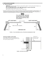
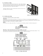
PIVOT ARM INSTALLATION - Location of Pivot Point 

Measurements are taken from the center of pivot of the gate hinge. 

The pivot arm needs to be securely mounted to the hinge post or equivalent mounting surface. It is recommended 
to weld the pivot arm to a metal post. In order to achieve the correct articulation, geometry and rate of speed of the 
gate it is critical that the measurements below are followed. The pivot arm may need to be cut to achieve the correct 
placement of the actuator mounting hole. Measurements are taken from the center of pivot of the gate hinge.

Vertical Position Of Pivot Arm

DIRECTION OF OPENING

GATES CLOSED

HINGE POST

HINGE POST

LEFT HAND SWING

RIGHT HAND SWING

TOP VIEW

6”

11”

6”

11”

The top edge of the Pivot Arm will be located 1/2” 

below the center line for the gate bracket. The 
Pivot Arm must be level when secured.

Hinge Post

Center line of attachment point 
for gate bracket

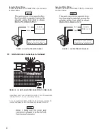
5.3 - Actuator mounting 

Mount the actuator to the pivot arm as shown. 

Please notice the washer goes below the actuator 

The lock nut should be tight to prevent movement or 
shifting when the actuator is running. This will also 
prevent excessive “bounce” or “wobble” when the gate 
stops moving.

FIGURE 5 - 4 HINGE POST

FIGURE 5 - 3 PIVOT ARM INSTALLATION

FIGURE 5 - 5 ACTUATOR MOUNTING

6

Содержание Titan 912L

Страница 1: ...ing Gate Operator Nice Gate Operators Titan 912L The Titan 912L Gate Operator is intended for use with vehicular swing gates The Titan 912L Gate Operator can be used in Class I Class II and Class III...

Страница 2: ...TABLE OF CONTENTS...

Страница 3: ...tor Motor Leads 9 Figure 5 16 Gate Bracket Mounting 9 Figure 5 15 Limit And Motor Connection To The Board 10 Figure 5 17 Limit Switch Adjustment 10 Figure 5 19 Learning Mode Open Limit 10 Figure 5 20...

Страница 4: ...icular Gate Operator Class III A vehicular gate operator or system intended for use in an industrial location loading dock area or other location not intended to service the general public 912L The Ti...

Страница 5: ...rements countles s AUTOMATIC GATES ARE NOT FOR PEDESTRIANS 3 SAFETY AND CAUTIONS WARNING IMPORTANT SAFETY INSTRUCTIONS WARNING TO REDUCE THE RISK OF INJURY OR DEATH READ AND FOLLOW ALL INSTRUCTIONS 3...

Страница 6: ...d should 3 3 Gate system safety devices 3 4 Infrared beams and warning signs 3 5 Establish the location 3 6 Read and follow all instructions 3 7 Keep children away 3 8 Test the gate system release 3 9...

Страница 7: ...fic to the appli cation in question with absolute safety in all considerations 4 3 35 Never mount any device that operates the gate opener where the user can reach around over or through the fate to o...

Страница 8: ...rcuit board is powered Doing so may damage the board beyond repair PULL TO OPEN INSTALLATION PIVOT ARM INSTALLATION Location of Pivot Point The following instructions provide up to 105 of swing Measur...

Страница 9: ...n from the center of pivot of the gate hinge Vertical Position Of Pivot Arm DIRECTION OF OPENING GATES CLOSED HINGE POST HINGE POST LEFT HAND SWING RIGHT HAND SWING TOP VIEW 6 11 6 11 The top edge of...

Страница 10: ...the front Do not use any battery with side terminals FIGURE 5 6 CONTROL BOX MOUNTING FIGURE 5 7 INCOMING POWER WIRING 5 5 Incoming power wiring Power input connections should be wired as follows Sola...

Страница 11: ...lue Encoder Power Green Yellow Blue Orange White Limits and Encoder White Close limit Orange Open Limit Green Limit Common Yellow Encoder Signal Blue Encoder Power Green Yellow Blue White Orange With...

Страница 12: ...ves in opposite direction from what is expected reverse the motor power lead wiring Black Red Motor 1 Motor 2 Install the 5 and 3 pin connector for motor 1 into the connection labeled Motor 1 on the c...

Страница 13: ...N press the OK button select Swing press OK select LIGHT AVERAGE or HEAVY depending on the gate and press OK a last time If done correctly the display should read LEARN with ENTER flashing below 13 Tu...

Страница 14: ...afety devices and start the learning sequence The gate will open partially then stop This is being done so that the control board can sense the type and operational condition of the drive motor The ga...

Страница 15: ...Momentarily shorting the digital input to GND opens the gate to the full open position with the subsequent auto close feature enabled Guard Station Stop 35 Dry contact input Normally Closed for a guar...

Страница 16: ...ice receiver may be removed from the Nice receiver memory without affecting other assigned remote controls This procedure needs to be performed at the Nice Plug In Receiver with the affected Nice remo...

Страница 17: ...iring system GREEN WIRE This ground connection will prevent dangerous currents from appearing on the metal control box the actuator or the gate itself DO NOT WIRE AC MAINS POWER TO THE METAL CONTROL B...

Страница 18: ...ng gate upon sensing an exiting vehicle 9 2 MAGNETIC LOCK CONNECTION 7 NC 8 Com Common 9 NO 10 GND 11 V Voltage is determined by incoming power supply This connection is used to install the magnetic l...

Страница 19: ...Common Ground FIGURE 10 1 RADIO RECEIVER 16 Damaged discolored or overheated equipment connections wiring bearing caps and installations Excessive heat or discoloration at high current carrying connec...

Страница 20: ...apment Protection Inputs Typical Installation Diagram Utilizing Photocells Loop Safety Loop Safety Loop Shadow Loop Exit 4 Min from closed gate 4 Min from closed gate 4 Min from open gate Photo 2 Phot...

Страница 21: ...als are not obstructed or impeded by building structures natural landscaping or similar obstruction DURING INSTALLATION DISCONNECT POWER at the control panel before making any electric service power c...

Страница 22: ...d remove key 3 Replace rubber key cover 4 Operator is now in Automatic Mode Manual Release Disengage FIGURE 13 3 MANUAL RELEASE DISABLE 1 Lift rubber key cover and insert key into lock and rotate 90 c...

Страница 23: ...f sudden impact force to the moving gate on a scale of 1 to 10 1 being most sensitive ESC Exit the FORCE menu 15 2 SPEED Max Sets the limit of maximum allowed gate speed on a scale of 20 to 100 20 bei...

Страница 24: ...r as required by the customer s installation requirements Set Language English Spanish French Set clock 12H 24H Set LCD Contrast Direction Motor Changes main motor direction Can only be performed in l...

Отзывы: