


Construction manual - Robot kit NIBO
burger
08.09.2015
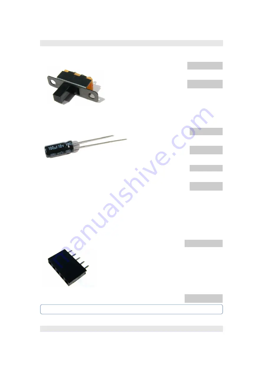
2.3.9.8 Switch
The toggle switch
S1
may be
soldered onto the board in
both possible orientations,
the functionality stays the
same.
2.3.10 Electrolytic capacitors
During placement of
the 470µF electrolytic
capacitors (
C1, C12
),
the 100µF electrolytic
capacitors (
C4, C5
)
and the two 4,7µF
electrolytic capacitors (
C21
und
C22
) onto the board
you
have to pay attention to the polarity!
The
short leg
must be placed into the
rectangular pad
!
The
positive
connections are marked with “+” sign on the board. The positive
pin of the electrolytic capacitor is the
long leg
and the negative one is the
short leg
. The negative connections are implemented as rectangular pads.
You can find a “-” symbol on the housing of the capacitor.
2.3.10.1 Straight sockets – 5 contacts
The
10
straight sockets with 5
contacts have to be soldered
into the pads
X1-X4
,
X8-X10
and
X11-X13
.
You don't have to pay attention
to the polarity.
X11-X13 are on board
, all other sockets are to find on board
http://nibo.
nicai-systems.de
51
Type
Part
Switch
S1
Value Part
470 µF C1
C12
100 µF C4
C5
4,7 µF
C21
C22
-
+
-
Type
Part
Straight
socket
5 contacts
X1
X2
X3
X4
X8
X9
X10
X11
X12
X13
Содержание NIBO burger
Страница 1: ...NIBO burger Robot Kit Construction manual version 2015 09 08...
Страница 21: ...Construction manual Robot kit NIBO burger 08 09 2015 Board second level http nibo nicai systems de 21...
Страница 59: ...Construction manual Robot kit NIBO burger 08 09 2015 Finished top side of board http nibo nicai systems de 59...
Страница 61: ...Construction manual Robot kit NIBO burger 08 09 2015 Finished top side of board http nibo nicai systems de 61...


