


!
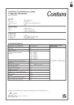
5 kW
615 mm
500 mm
355 mm
85 kg
GB
3
Installation by authorised
technician
This manual contains instructions about how
the stoves must be assembled and installed. To
ensure the function and safety of the stove, the
installation should be carried out by a Hetas
trained engineer. Contact one of our dealers who
can recommend suitable installer. When completed,
the installer should inform the local Council/
authority about the new installation.
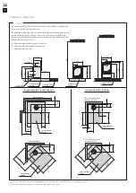
Building application
These main instructions may give guidance which
would contravene national building regulations.
Please refer to supplementary instructions or ask
your local authority for advice regarding building
regulations.
Before installing a stove or erecting a chimney it
is necessary for you to make a building application
permission to your local authority.
The owner of the house is personally responsible
for ensuring compliance with the mandatory safety
requirements and must have the installation
approved by a qualified inspector. Your local
chimney sweep must also be informed about the
installation as this will affect the routines for
regular chimney-sweeping services.
Structural support
Check that the wood joists are strong enough to
bear the weight of the stove and chimney. The
stove and chimney can usually be placed on a
normal wooden joist in a single occupancy house if
the total weight does not exceed
400 kg.
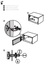
Hearth plate
Due to the risk of falling embers, a flammable
floor must be protected by a hearth plate. It must
extend 300 mm in front of the stove and 100
mm on each side of the stove, or have a 200 mm
extension on each side of the opening. The hearth
plate can consist of natural stone, concrete, metal
plate or glass.
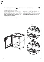
Final inspection of the
installation
It is extremely important that the installation
is inspected by an authorised chimney sweep
before the stove is used. Also read the ”Lighting
instructions”, before lighting for the first time.
Nominal effect
5 kW
Efficiency
80,3%
Meets requirements of:
European standard EN-13240
Clean Air Act. 61534 (UK)
NS 3059 (NO)
The stove becomes very hot
During operation, certain surfaces of the
stove become very hot and can cause
burn injury if touched. Be aware of the
strong heat radiated through the hatch
glass. Placing flammable material closer
than the safe distance indicated may
cause a fire. Pyre lighting can cause quick
gas ignition with the risk of damage to
property and personal injury.
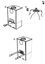
Connection to chimney
• The stove must be connected to chimneys dimensioned for a minimum flue
gas temperature of 400°C.
• The stove should not be installed in a chimney serving more than one
appliance.
• The diameter of the connection sleeve is designed to fit chimney pipes
with an external diameter of Ø125 mm. A connection sleeve is available,
as an optional extra, for chimney pipes with an internal diameter of Ø150
mm.
• Normal chimney draw under nominal operation should be between 20-25
Pa close to the connector. The draft is affected both by the length and
area of the chimney, and by how well sealed it is. Minimum recommended
chimney length is 3.5 m and suitable cross section area is 120-175 cm²
(125-150 mm in diameter).
• A flue with sharp bends and horizontal routing reduces the draught in
the chimney. Maximum horizontal flue is 1 m, on the condition that the
vertical flue length is at least 5 m.
• It must be possible to sweep the full length of the flue and the soot
hatches must be easily accessible.
• Carefully check that the chimney is sealed and that there is no leakage
around soot hatches and flue connections.
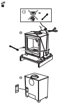
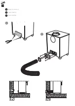
Supply of combustion air
When a stove is installed in a room, the demand for air supply to the room
increases. Air can be provided indirectly via a vent in the outer wall or via a
duct from the outside that is connected to the connector on the underneath
of the stove. The amount of air needed for combustion is 20 m
3
/h.
The connector (accessory) for the combustion air has an external diameter
of 80 mm. When duct routing further than 1 m the pipe diameter must
be increased to 100 mm and a correspondingly larger wall vent must be
selected.
In hot areas, the duct should be insulated with 30 mm mineral wool with a
moisture inhibiting outer cover. It is also important to seal around the hole
in the wall (or floor) of the lead-in using sealant.
A 1 m length of condensation insulated ducting for combustion air is
available as an accessory.
Facts
Contura reserves the right to change dimensions and procedures described in these instructions
at any time without special notice. The current edition can be downloaded from www.contura.eu
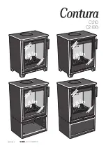
Содержание Contura C210
Страница 1: ...C210 C210G contura eu ...
Страница 8: ...16 10 10 VA NA DIU M No 7 CHROME 1 2 LEK 10 10 VA NA DI UM No 7 CHRO M E ...
Страница 10: ...18 HK HK 1 2 SE GB NO Tilluft Tillbehör Supply Accessory Tilluft Tilbehør ...
Страница 11: ...19 1 3 2 ...
Страница 13: ...21 7 5 6 ...
Страница 15: ...23 1 2 SE GB NO Placering på vedfack Tillbehör Positioning the log box Accessory Plassering av vedrom Tilbehør ...
Страница 16: ...24 4 5 3 ...
Страница 17: ...25 6 7 8 ...
Страница 19: ......
Страница 20: ...811482 IAV SE EX C210 2 2022 08 31 NIBE AB Box 134 285 23 Markaryd Sweden contura eu ...


