


Electrical connection
ON
12345678
-X9
-X2
24
20
21
22
23
15
16
17
18
19
10
11
12
13
14
5
6
7
8
9
1
1
N
L
PE
PE
1
2
3
4
5
6
7
8
2
3
4
5
6
7
8
9
2
3
4
-X8
-X4
-X10
-X1
$$;
$$;
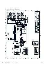
NOTE
All electrical connections must be carried out by
an authorised electrician.
Electrical installation and wiring must be carried
out in accordance with the stipulations in force.
F1345 must not be powered when installing
AXC 50.
Connection of sensors and external blocking
Use cable type LiYY, EKKX or similar.
Flow temperature sensor, cooling (BT64)
Connect the flow temperature sensor to AA5-X2:21-22.
Return line sensor, cooling (BT65)
Connect the return line sensor to AA5-X2:19-20.
External blocking
A contact (NO) can be connected to AA5-X2:23-24 to
block cooling operation. When the contact closes, cooling
operation is blocked.
24
20
21
22
23
15
16
17
18
19
13
14
$$;
([WHUQDO
8QLW ER[
([WHUQDO EORFNLQJ
%7
%7
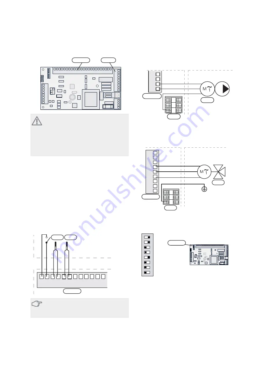
Caution
The relay outputs on the accessory card can have
a max load of 2 A (230 V) in total.
Connection of the circulation pump (GP13)
Connect the circulation pump (GP13) to AA5-X9:2 (230
V), AA5-X9:1 (N) and X1:3 (PE).
1
2
3
4
L
N
PE
3
2
1
8QLW ER[
([WHUQDO
*3
$$;
;
Connection of the mixing valve motor (QN18)
Connect the mixing valve motor (QN18) to AA5-X9:6
(230 V, open), AA5-X9:5 (N) and AA5-X9:4 (230 V, close).
1
2
3
4
5
6
7
8
9
3
2
1
6+
1
6+
2SHQ
&ORVH
3(
41
8QLW ER[
([WHUQDO
$$;
;
DIP switch
The DIP switch on the accessory card must be set as fol-
lows.
ON
12345678
ON
12345678
-X9
-X2
24
20
21
22
23
15
16
17
18
19
10
11
12
13
14
5
6
7
8
9
1
1
N
L
PE
PE
1
2
3
4
5
6
7
8
2
3
4
5
6
7
8
9
2
3
4
-X8
-X4
-X10
-X1
AA5-S2
Relay output for cooling mode indication
It is possible to have an external indication of cooling
mode indication through the relay function via a potential
free variable relay (max 2 A) on terminal block X5.
If cooling mode indication is connected to terminal block
X5 it must be selected in menu 5.4.
AXC 50
Chapter 8 |
Passive cooling (4-pipe)
30
Содержание AXC 50
Страница 1: ...Installer manual LEK AXC 50 Accessories IHB GB 1222 1 231158...
Страница 2: ......
Страница 10: ...Electrical circuit diagram AXC 50 Chapter 3 Shunt controlled additional heat 8...
Страница 15: ...Electrical circuit diagram 13 Chapter 4 Step controlled additional heat AXC 50...
Страница 21: ...Electrical circuit diagram 19 Chapter 5 Extra climate system AXC 50...
Страница 26: ...Electrical circuit diagram AXC 50 Chapter 6 Hot water comfort 24...
Страница 29: ...Electrical circuit diagram 27 Chapter 7 Groundwater pump AXC 50...
Страница 34: ...Electrical circuit diagram AXC 50 Chapter 8 Passive cooling 4 pipe 32...
Страница 40: ...Electrical circuit diagram AXC 50 Chapter 9 Passive cooling 2 pipe 38...
Страница 46: ...Electrical circuit diagram AXC 50 Chapter 10 Passive active cooling 2 pipe 44...
Страница 47: ......
Страница 48: ...NIBE AB Sweden Hannabadsv gen 5 Box 14 SE 285 21 Markaryd info nibe se www nibe eu 231158...


