background image

NI USB-6000 User Guide

|

© National Instruments

|

5

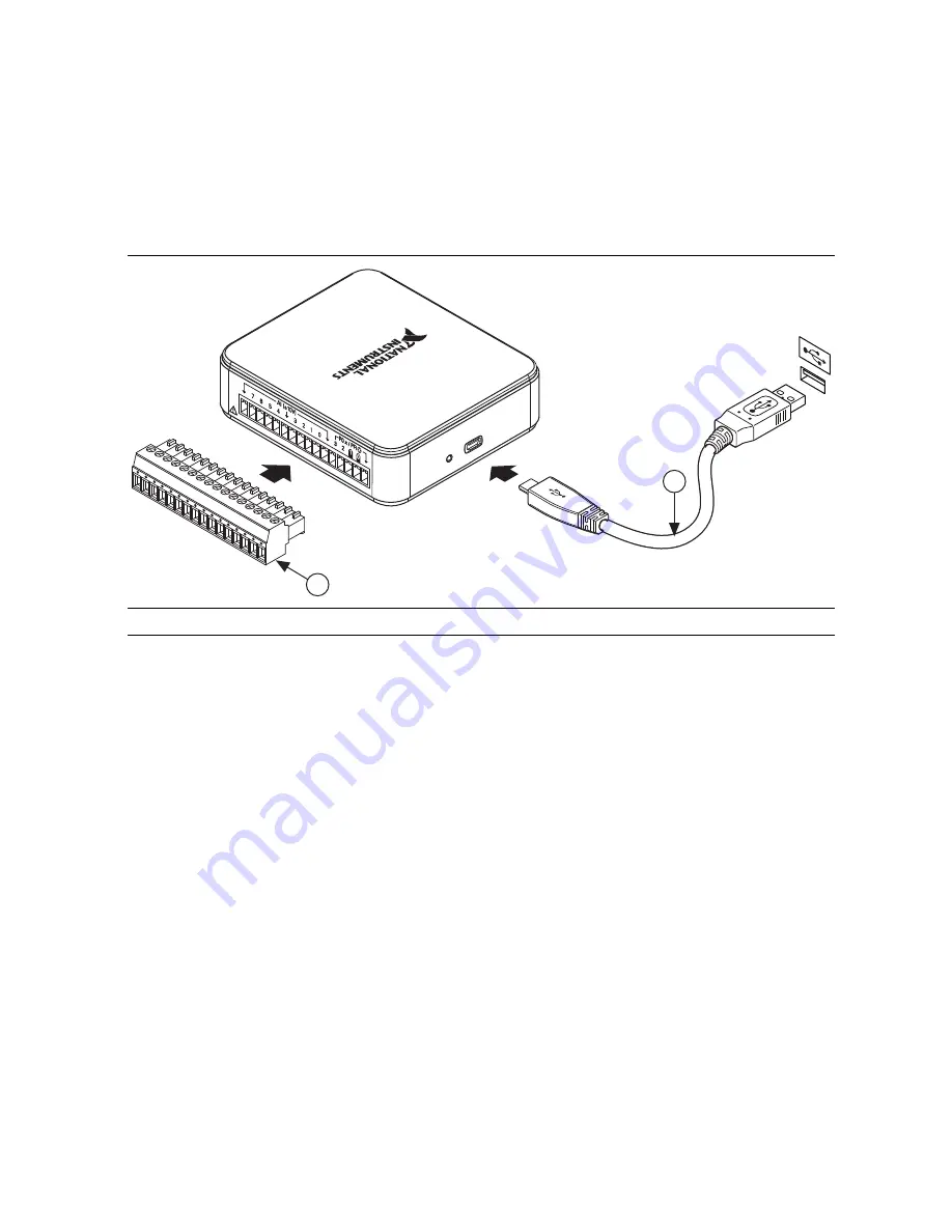
Preparing the Hardware

1.

Insert the screw terminal connector plug into the connector jack on the device. Refer to 
Figure 2.

2.

The Hi-Speed USB cable has two different connectors on each end. Plug the smaller 
Micro-B USB connector into the device, and plug the larger USB connector into a 
USB port. Refer to Figure 2.

Figure 2.  

Hardware Setup for NI USB-6000

Verifying the Installation

1.

Launch Measurement & Automation Explorer (MAX) by double-clicking the 

NI MAX


icon on the desktop, or 

(Windows 8)

 by clicking 

Measurement & Automation Explorer 

from NI Launcher. 

2.

Expand 

My System»Devices and Interfaces

 and verify that the NI USB-6000 is listed. 

If your device does not appear, press <F5> to refresh the view in MAX. If your device is 
still not recognized, refer to 

ni.com/

s

upport/daqmx

 for troubleshooting information.

3.

Right-click your device and select 

Self-Test

. When the self-test finishes, a message 

indicates successful verification or if an error occurred. If an error occurs, refer to 

ni.com/

s

upport/daqmx

.

4.

Connect the wires (1.31 to 0.08 mm

2

, or 16 to 28 AWG) to the screw terminals by stripping 

6.35 mm (0.25 in.) of insulation, inserting the wires into the screw terminals, and securely 
tightening the screws. Refer to Figure 4 for the NI USB-6000 pinout. 

5.

Right-click your device and select 

Test Panels

. A test panel appears. 

6.

Click 

Start

 to test the device functions, or 

Help

 for operating instructions. If an error 

message is displayed, refer to 

ni.com/

s

upport/daqmx

7.

Click 

Close

 to exit the test panel. 

1

Screw Terminal Connector Plug

2

Hi-Speed USB Cable

1

2

Содержание USB-6000

Страница 1: ...ta acquisition DAQ device The NI USB 6000 is a USB device that provides eight single ended analog input AI channels four digital input output DIO channels and a 32 bit counter Figure 1 NI USB 6000 Top...

Страница 2: ...atures 7 Block Diagram 7 LED Indicator 7 Cables and Accessories 8 Pinout and Signal Descriptions 9 Analog Input 10 Connecting Analog Input Signals 11 Wiring Considerations 12 AI Start Trigger 13 Digit...

Страница 3: ...environment it must be in a suitably rated enclosure Electromagnetic Compatibility Guidelines This product was tested and complies with the regulatory requirements and limits for electromagnetic comp...

Страница 4: ...stall a damaged device in your computer Store the device in the antistatic package when the device is not in use Packing List The NI USB 6000 is shipped in a box that contains NI USB 6000 Screw termin...

Страница 5: ...oes not appear press F5 to refresh the view in MAX If your device is still not recognized refer to ni com support daqmx for troubleshooting information 3 Right click your device and select Self Test W...

Страница 6: ...tion LabVIEW Go to Help LabVIEW Help Next go to Getting Started with LabVIEW Getting Started with DAQ Taking an NI DAQmx Measurement in LabVIEW LabWindows CVI Go to Help Contents Next go to Using LabW...

Страница 7: ...d On not blinking Device connected and functioning normally Blinking Device has encountered an error Wait 10 seconds to allow the device to attempt to recover from the error If the LED keeps blinking...

Страница 8: ...the NI USB 6000 product page at ni com Table 3 NI USB 6000 Cables and Accessories Accessory Part Number Description USB 6000 Accessory Kit 782703 01 Four additional screw terminal connectors and a sc...

Страница 9: ...gital signals AI GND Analog Input Ground The reference point for analog input measurements P0 0 3 D GND Input or Output Port 0 Digital I O Channels 0 to 3 Configure each signal individually as an inpu...

Страница 10: ...analog to digital converter ADC digitizes the AI signal by converting the analog voltage into digital code AI FIFO The NI USB 6000 can perform both single and multiple analog to digital conversions of...

Страница 11: ...shown in Figure 6 Figure 6 Connecting a Referenced Single Ended Voltage Signal Signals of 10 V at any analog input pin with respect to AI GND are accurately measured Beyond 10 V the input signal will...

Страница 12: ...ider using an NI DAQ device with differential inputs Noise coupling is one of the main error sources in measurements Electrostatic and magnetic noise coupling are the result of differences in the sign...

Страница 13: ...nce can appear as measurement error Follow the connection instructions for grounded signal sources to eliminate this ground potential difference from the measured signal Wiring Ground Referenced Signa...

Страница 14: ...t liable for any damage resulting from such signal connections Power On States At system startup and reset the hardware sets all DIO lines to high impedance inputs The DAQ device does not drive the si...

Страница 15: ...do not connect it to any external signal source ground signal or power supply If you configure a DIO line as an output understand the current requirements of the load connected to these signals Do not...

Страница 16: ...ation or add example code to an existing application To locate NI software examples go to ni com info and enter the Info Code daqmxexp For additional examples refer to zone ni com To run examples with...

Страница 17: ...ions palettes menus and tools Refer to the following locations on the Contents tab of the LabVIEW Help for information about NI DAQmx Getting Started with LabVIEW Getting Started with DAQ Includes ove...

Страница 18: ...ted with the Measurement Studio Class Libraries To create an NI DAQmx application using Visual Basic NET or Visual C follow these general steps 1 In Visual Studio select File New Project to launch the...

Страница 19: ...d user guides manuals are available as PDFs You must have Adobe Reader 7 0 or later PDF 1 6 or later installed to view the PDFs Refer to the Adobe Systems Incorporated Web site at www adobe com to dow...

Отзывы: