
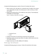


1. Make sure that no I/O-side power is connected to the I/O module. If the system
is in a nonhazardous location, the chassis power can be on when you remove
I/O modules.
2. Squeeze the latches on both sides of the module and pull the module out of
the chassis.
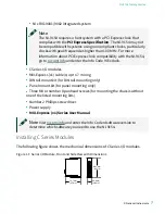
Connecting the NI 9154 to Ground
You must connect the NI 9154 grounding terminal to the grounding electrode
system of the facility.
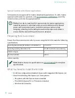
What to Use
■
Ring lug
■
Wire, 2.05 mm
2
(12 AWG) or larger
■
Screwdriver, Phillips #2
What to Do
Complete the following steps to ground the NI 9154.
1. Attach the ring lug to the wire.
2. Remove the grounding screw from the grounding terminal on the NI 9154.
3. Attach the ring lug to the grounding terminal.
4. Tighten the grounding screw to 0.5 N · m (4.4 lb · in.) of torque.
5. Attach the other end of the wire to the grounding electrode system of your
facility using a method that is appropriate for your application.
Caution
If you use shielded cabling to connect to a C Series module with
a plastic connector, you must attach the cable shield to the chassis
grounding terminal using 1.3 mm diameter (16 AWG) or larger wire. Attach
a ring lug to the wire and attach the wire to the chassis grounding
© National Instruments
9
NI-9154 Getting Started
Содержание NI-9154
Страница 1: ...NI 9154 Getting Started 2022 07 06...


