


User Manual: BlueBoard-LPC214X
Revision 1.3
9
3.2
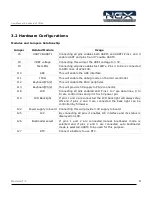
Hardware Configurations
Modules and Jumpers Relationship
Jumper
Related Module
Usage
J6
UART0 &UART1
Connecting all pins enables both UART0 and UART1.Pins 1 and 3
enable UART and pins 5 and 7 enable UART0.
J8
VREF voltage
Connecting this will set the VREF voltage to 3.3V.
J9
Test LEDs
Connecting all pins enables test LED's. Pins 3 to 9 are connected
to SPI0 lines of LPC2148.
J10
ADC
This will enable the ADC interface
J11
JTAG
This will enable the debug mode on the microcontroller.
J12
Keyboard(PS/2)
This will enable the PS/2 peripheral.
J13
Keyboard(PS/2)
This will provide 5V supply to PS/2 connector.
J18
LCD
Connecting all pins enabled LCD. Pins 1 to 7 are data lines, 9 to
13 are control lines and pin 15 is 5V power pin.
J19
LCD Backlight
If pins 1 and 2 are connected the LCD back light will always stay
ON and if pins 2 and 3 are connected the back light can be
controlled by firmware.
J22
Power supply to board Connecting this will provide 3.3V supply to board.
J25
I2C
By connecting all pins it enables I2C interface and its status is
displayed on LCD.
J26
Bootloader select
If pins 1 and 2 are connected,manual bootloader mode is
selected and if pins 2 and 3 are connected auto bootloader
mode is selected.UART0 to be used for this purpose.
J27
RTC
Connect a battery to use RTC.