NGX Technologies BlueBoard-LPC214X Скачать руководство пользователя страница 17


User Manual: BlueBoard-LPC214X  
 

Revision 1.3 

17 

3.2.7  Buzzer 

Test setup: 

Connect jumper to J23, when the board is turned on or RESET you will hear a beep after few seconds. 

This is how the user can confirm the status of the Buzzer. 


3.2.8  SD/MMC connector 

Test setup: 

Insert a SD card in the SD card holder (J24), the status of the SD card will be displayed on LCD upon 

power cycle or reset of the BlueBoard. If the SD card is inserted properly “SD card – OK” is displayed on LCD else it 
displays “SD card- Not OK”. During manufacturing the board is tested with Kingston’s 1GB SD card. 


Note: The SD/MMC card being tested should be formatted with FAT file system (Not FAT32 or NTFS format). 


3.2.9  Audio jack 

Test setup: 

Connect a headset to the audio jack connector. You should hear a ding sound being played. The sound 

is heard only for few seconds after power ON or RESET. 


3.2.10  PS/2 keyboard 

Test setup: 

To enable PS/2 connect jumper to J15. Connect a PS/2 keyboard to this connector. Now press any key 

on the keyboard. The user can see which key he/she has pressed on the LCD. 
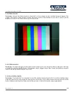
 

3.2.11  LCD display 

Test setup: 

To enable the LCD connect jumpers to all pins of J18. A default message “NGX TECHNOLOGIES” will 

be displayed and later status of SD/MMC and I2C is displayed. The back light of LCD can be controlled by connecting 
jumper to appropriate pins of J19. The contrast of LCD can be varied using the POT. 


3.2.12  RTC : 

A  2- pin connector J27 is provided for RTC.Connect an external battery to use the to this connector to 

work with RTC. 


3.2.13 ADC : 

The ADC port is given to a POT. To test the ADC rotate the POT, as the POT position varies the output 

number of LEDs that are turned ON varies. 

Содержание BlueBoard-LPC214X

Страница 1: ...User Manual BlueBoard LPC214X Revision 1 3 1 USER MANUAL BlueBoard LPC214X...

Страница 2: ...The user assumes all responsibility and liability for proper and safe handling of the goods Further the user indemnifies NGX Technologies from all claims arising from the handling or use of the goods...

Страница 3: ...ed a note in section 3 2 8 for the SD MMC connector regarding the card file format Updated the USB Virtual COM Port Installation for Windows XP section Revision 1 1 to Revision 1 2 Added a known issue...

Страница 4: ...ARTING OFF 6 2 2 1 Connecting the hardware 6 2 2 2 Programming BlueBoard 6 3 BLUEBOARD HARDWARE 8 3 1 FUNCTIONAL OVERVIEW 8 3 2 HARDWARE CONFIGURATIONS 9 4 BLUEBOARD UTILITIES 18 4 1 OVERVIEW 18 4 2 S...

Страница 5: ...power LED On board linear regulators generate 3 3V 500mA and 5v 500mA from power supply USB connector as alternate power source Connectors Extension headers for all microcontroller pins RS232 connecto...

Страница 6: ...mware which can test all the peripherals 2 2 2 Programming BlueBoard BlueBoard can be programmed through wiggler clone JTAG or through serial port using Flash Magic Flash Magic is a freeware windows u...

Страница 7: ...ode under the Options tab select Advanced options In this under Hardware Config tab make sure the options Use DTR and RTS to control RTS and P0 14 and Keep RTS asserted while COM port open are checked...

Страница 8: ...3 1 Functional Overview LPC214x 74HC595 DB9 Female Connector for UART1 DB9 Female Connector for UART0 USB Type B connector 2x16 CHARACTERS LCD DISPAY VGA Female connector JTAG PS 2 KEYBOARD AUDIO OUT...

Страница 9: ...the PS 2 peripheral J13 Keyboard PS 2 This will provide 5V supply to PS 2 connector J18 LCD Connecting all pins enabled LCD Pins 1 to 7 are data lines 9 to 13 are control lines and pin 15 is 5V power...

Страница 10: ...Please note that all the LEDs should glow this confirms the working of LEDs Now since the LEDs are connected through a serial to parallel converter this test also confirms the working of SPI0 of the...

Страница 11: ...ual BlueBoard LPC214X Revision 1 3 11 A Connect To window opens where you have to select the COM port In this example it is COM1 Click OK A COM1Properties window appears Set the values as shown below...

Страница 12: ...User Manual BlueBoard LPC214X Revision 1 3 12 Next an empty BlueBoard Hyper Terminal window opens as shown...

Страница 13: ...ision 1 3 13 Now make sure that the BlueBoard is powered and the serial port is connected to the respective port to be tested UART0 or UART1 By pressing any key from keyboard the following message wil...

Страница 14: ...UART0 can also be used for serial programming If the selected bootloader mode is Manual then Half modem cable should be used else if it is in Auto mode use full modem cable Note that after programmin...

Страница 15: ...OM Port Installation for Windows XP section Test setup Connect the USB cable to USB connector The power LED D14 and USB connect LED D10 turn ON The USB enumeration can be checked in device manager The...

Страница 16: ...on the board connect jumper to J11 and connect the JTAG to debug port We have successfully tested the BlueBoard with JTAG interface using a Wiggler Clone JTAG To test this feature you need to have the...

Страница 17: ...jack connector You should hear a ding sound being played The sound is heard only for few seconds after power ON or RESET 3 2 10 PS 2 keyboard Test setup To enable PS 2 connect jumper to J15 Connect a...

Страница 18: ...rocontrollers Any toolchain can be used as long as it is able to generate the necessary files for downloading onto the BlueBoard Here are few toolchain suggestions GNUARM ToolChain http winarm science...

Страница 19: ...file is not unpacked in Windows by default and needs to be extracted from a Windows cab file which should be in the C WINDOWS Driver Cache i386 directory for Windows XP SP2 Change directory to C WIND...

Страница 20: ...cally then the user needs to go the Device Manager window and right click on the device and select update driver Set the new hardware Wizard to search a specific location for the driver and specify th...

Страница 21: ...gned to the USB serial device is not fixed and can change To know the current COM port number the user needs to look into the Device Manager page under Ports COM LPT After selecting the appropriate CO...

Страница 22: ...User Manual BlueBoard LPC214X Revision 1 3 22 6 Schematics A PDF version of the schematic can be downloaded from http blueboard lpc214x googlecode com files BlueBoard_schematics_V1R1 pdf...

Страница 23: ...4x source checkout Analog to Digital Converter UART I2C E2PROM Driver Reading and writing to an i2c e2prom SPI Using SPI in polled master mode to drive 8x LEDs FIQ Handler VGA Timer Soft Timer Demonst...

Страница 24: ...214X Revision 1 3 24 8 Known Issues AUTO mode ISP and full modem cable While using the Auto program mode for ISP after programming the Blueboard the user needs to unplug the full modem serial cable fo...

Отзывы: