


Nexxt Solutions - 24 port gigabit switch
Nexxt Solutions - 24 port gigabit switch
1. RJ-45-ports
2. LED status indicators
3. Metal housing
4. Mode selection button
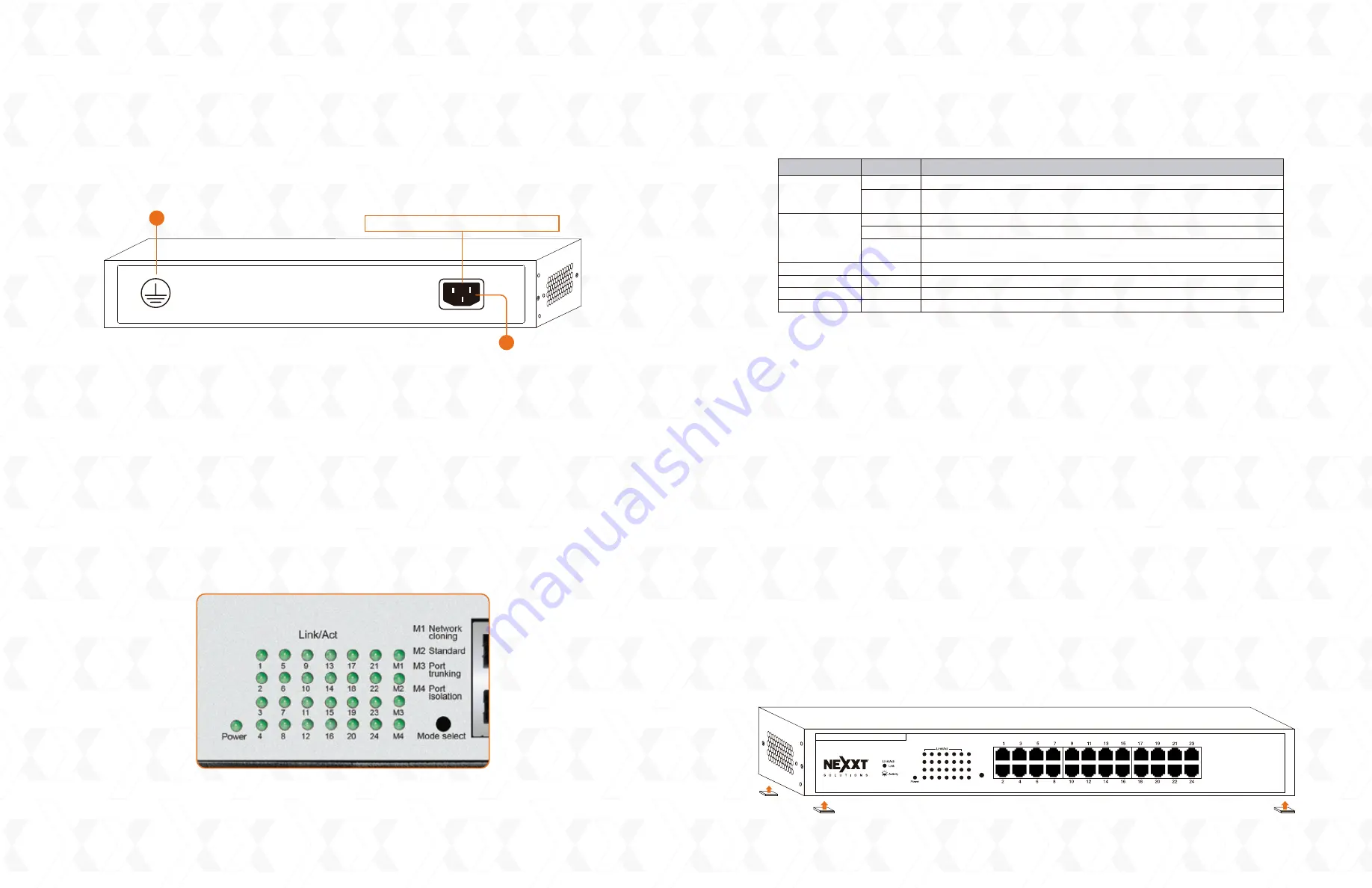
On the rear panel, there is the AC power jack with the input range marked.
1. Protective ground screw
2. AC input
Note:
Please use the supplied power cord only. The use of any other cable may damage the
unit and void the warranty.
1.4 LED description
LED indicators provide information about the connection and Link/ACT status of the switch.
They also facilitate activity monitoring and troubleshooting the performance of the network.
The following chart shows the LED indicators of the switch along with an explanation of each
indicator.
2. Installation
2.1 Preliminary steps
Observe the safety instructions detailed below before connecting the device into your
network
• Select a location with adequate ventilation all around the unit.
• Place the switch on a secure, stable and clean surface.
• Allow at least 10cm clearance between the rear panel and the wall to dissipate hot air.
• Never place heavy objects on top of the switch.
• If you need to stack other devices on top of the switch, a minimum separation of
1.5 cm should be used.
• Electrical power supplied should match the voltage specified.
2.2 Installation procedures
The switch can be mounted in a rack or placed free-standing on a desktop.
2.2.1 Installation on a flat surface
Attach the four self-adhesive rubber pads (supplied) in each corner on the bottom of the
chassis
Rear panel
100-240V~0.5A-5060Hz
Power Receptacle: 100-240V Input
LED panel
The switch is powered on
The switch is either turned off, the connection is loose or there might be
a problem with the power cord or outlet
The corresponding port is correctly connected
The port is actively receiving or transmitting data packets
The port is either disconnected or the switch is improperly connected to
the remote device
Network cloning mode
Standard mode
Port trunking mode
Port isolation mode
Solid
Off
Solid
Blinking
Off
Solid
Solid
Solid
Solid
Power
Link/Act
M1
M2
M3
M4
LED indicator
Description
Status
Mode select
M1 Network
cloning
M2 Standard
M3 Port
trunking
M1 Port
isolation
24- Port Gigabit Ethernet Switch
Axis2400R
23 (Uplink)
24 (Uplink)
Attach the rubber pads to the bottom of the unit
1
2


