8
DR 4305 NexStar Installation and Operation
T
ERMINATION
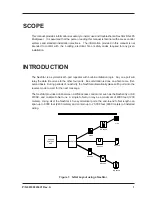
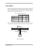
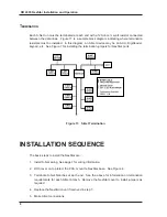
Each S-Net run must be terminated at each end with a 120-ohm, ¼ watt resistor connected
between the data lines. Figure 11 is a sample block diagram indicating where termination
resistors must be installed. In this diagram, an S-Net device may be an ACU, DigiReader,
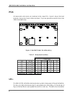
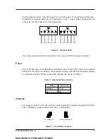
keypad, etc. See Figure 7 for installing the termination jumpers for NexStar ports.
Figure 11: S-Net Termination
INSTALLATION SEQUENCE
The basic steps to install the NexStar are:
1. Install S-Net wiring. See page 7 for wiring information
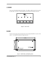
2. With cover on to protect the PCA, mount te NexStar base. See Figure 4.
3. Terminate S-Net branches at each end. See the above for information on termination
requirements for each S-Net branch. Remove the NexStar cover to install jumpers as
required.
4. Replace the NexStar cover if removed in step 3.
5. Make S-Net connections.

