4
DR 4305 NexStar Installation and Operation
PCA
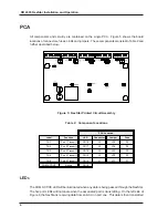
All components and circuitry are contained on the single PCA. Figure 5 shows the board
locations of connectors, fuses, LEDs and jumpers. These components are listed in Table 2 and
further described below.
Figure 5: NexStar Printed Circuit Assembly
Table 2: Component Locations
PCA Location
Label
Function
LED
Connector
Jumper
Fuse
TX-1
Port 1 Transmit
CR18
J5
JP5
F5
TX-2
Port 2 Transmit
CR17
J4
JP4
F4
TX-3
Port 3 Transmit
CR16
J3
JP3
F3
TX-4
Port 4 Transmit
CR15
J2
JP2
F2
TX-5
Port 5 Transmit
CR14
J1
JP1
F1
COM ACTIVE
Active
CR19
LED
S
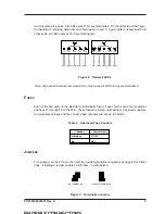
The COM ACTIVE LED will be illuminated when any data is being passed through the NexStar.
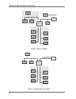
The five port LEDs will illuminate when the associated port is transmitting. On the left side of
Figure 6, the NexStar is receiving data from an ACU on port one. This data is then transmitted


