


Xperience platform
All of Nexmosphere’s controllers are built on the same platform principles. If this is your first time using a Nexmosphere
controller, we recommend to first read
https://nexmosphere.com/technology/xperience-platform/
to learn the basics about
our platform and its terminology.
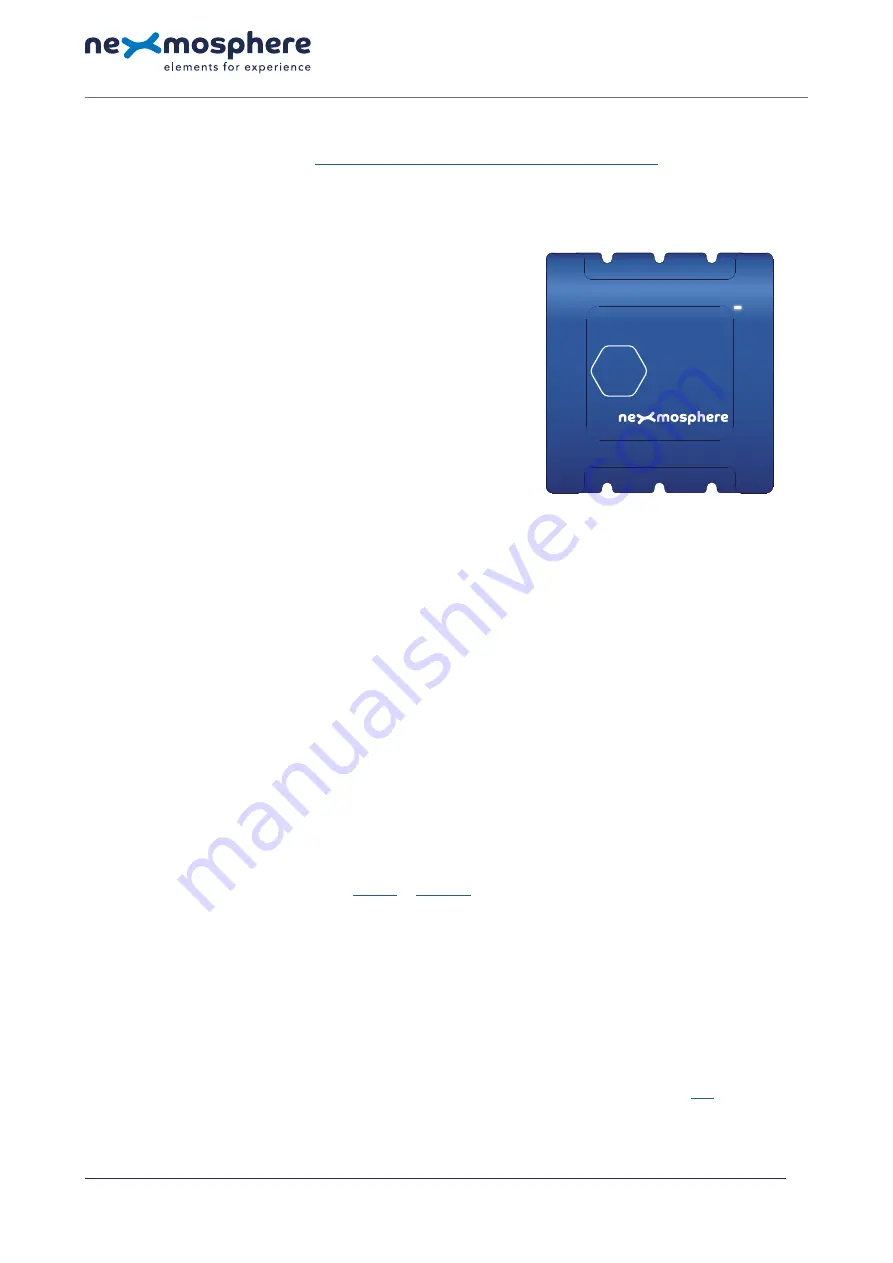
XC-741
The XC-741 is an Xperience controller with 8 X-talk interfaces and
4 X-Wave interfaces:
1.
X-talk interface 001
5.
X-talk interface 005
2.
X-talk interface 002
6.
X-talk interface 006
3.
X-talk interface 003
7.
X-talk interface 007
4.
X-talk interface 004
8.
X-talk interface 008
111.
X-Wave interface, API address 111
112.
X-Wave interface, API address 112
113.
X-Wave interface, API address 113
114.
X-Wave interface, API address 114
USB.
API interface (micro-USB connector)
LED.
White status LED
DC.
12-24VDC Power input (2.1mm DC socket)
Hardware setup
1.
Connect one or more Elements to any of the 8 X-talk interfaces.
2.
Connect one or more Pixel LED strips to any of the 4 X-Wave interfaces*.
3.
Connect the 12 or 24VDC power supply to the DC power input connector.
4.
Connect the micro-USB cable to a 3rd party device (e.g. Digital Signage Player or PC).
5.
Wait until the white status LED stops blinking. This lasts about 5 seconds.
*
Pixel LED strips including connection cable are available as an accessory (product codes L-P......W). If you want to connect your own Pixel LED strips, separate
connection cables are also available as an accessory (product codes CAW-S..C).
Software setup for testing (Terminal)
Typically, the XC-741 controller is connected to a 3rd party device, such as a Digital Signage Player, on which CMS software is installed that has built-in
functionality for sending and receiving Serial Events. However, if you want to do a first test on a PC or Mac, follow the instructions below:
1.
Download a terminal program. For example
or
2.
Open the Terminal program and go to settings. Choose the COM port on which the XC-741 controller enumerated*.
In most cases this is the highest available number in the COM port drop-down setting.
3.
Set the COM port settings to the following values
Baudrate
115200
Flow Control
None
Parity
None
EOL
CR+LF
Data
Bits 8
Protocol
ASCII
Stop
Bits 1
4.
Set the COM port to “Open”.
The controller is now ready for use.
5.
When sending consecutive API serial commands to the XC-741 controller, place a 50mS delay between each command.
*
In case the XC-741 controller is not recognized as a COM port by the 3rd party device, a driver (Prolific PL2303) can be downloaded
N ex m o s p h e re
H i g h Te c h C a m p u s 1 0 ( M μ b u i l d i n g )
5 6 5 6 A E E i n d h ove n • T h e N e t h e r l a n d s
T
+ 3 1 4 0 2 4 0 7 0 7 0
E
s u p p o r t @ n ex m o s p h e re.c o m
QUICK START GUIDE
XC-741 XPERIENCE CONTROLLER
© 2020 Nexmosphere. All rights reserved. v1.0 / 05-20
All content contained herein is subject to change without prior notice.
1
USB
DC
LED
XC
4
5
2
7
3
6
1
111
112
113
114
8


