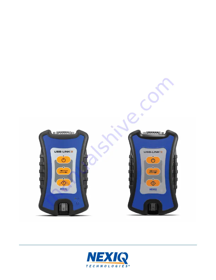
USB-Link™ 3
Installation and Setup Manual
Wireless Edition
PN 121052
Wired Edition
PN 121054
Страница 1: ...USB Link 3 Installation and Setup Manual Wireless Edition PN 121052 Wired Edition PN 121054 ...
Страница 2: ...ty for any errors or inaccuracies that may appear in this book Except as permitted by such license no part of this publication may be reproduced or transmitted in any form or by any means electronic mechanical or otherwise without the prior written permission of IDSC Holdings LLC NEXIQ Technologies and USB Link are trademarks of IDSC Holdings LLC 2022 IDSC Holdings LLC All rights reserved All othe...
Страница 3: ...leshooting 4 Specialized Text 4 Chapter 2 Introducing the USB Link 3 5 Component Checklist 6 Product Specifications 7 System Requirements 8 Device Features 9 Communication Options Wired vs Wireless 12 Wired USB Connection 12 Wireless Bluetooth Connection 13 Wireless Wi Fi Connection 14 Mini Access Point Mode Peer to Peer 15 Infrastructure Mode Connecting to your Company s Network 16 ...
Страница 4: ... a Vehicle 27 Making a Wired USB Connection 28 Making a Wireless Bluetooth Connection 29 Pair the Device 30 Making a Wireless Wi Fi Connection 32 Mini Access Point Mode 32 Infrastructure Mode 35 Step 3 Test the Connection 36 Using the USB Link 3 Explorer Utility 40 The Configuration Tab 42 Switching Modes Mini Access Point and Infrastructure 43 The File Menu 45 The Tools Menu 46 Ping 46 Options 47...
Страница 5: ...ns pg 3 Special Messages pg 3 Note pg 3 Important pg 3 Caution pg 3 Warning pg 4 Troubleshooting pg 4 Specialized Text pg 4 This chapter provides an overview of this manual s organization and the conventions used throughout NOTE Images used throughout this manual are for illustrative purposes only 1 ...
Страница 6: ...nual provides an overview of this user manual Chapter 2 Introducing the USB Link 3 Wireless Edition and Wired Edition provides details on communication options including Bluetooth Wi Fi USB Mini Access Mode and Infrastructure Mode Chapter 3 Installing the Drivers and Setting up the Device provides instructions for installing NEXIQTM drivers and utilities connecting to a vehicle pairing the device ...
Страница 7: ...ed Example Important IMPORTANT indicates a situation which may damage the test equipment or vehicle Example Caution CAUTION indicates a potentially hazardous situation which may result in minor or moderate injury to the operator or bystanders Example NOTE Refer to the page number indicated for further details on the described component IMPORTANT Keep all cables clear of moving or hot engine parts ...
Страница 8: ...ortant information FEATURE Used to highlight the name of a specific feature Example Click on the Finish button to continue Field Line Used to highlight the name of a field or a line of text from a display Example A check mark is placed in the check box next to the Total Fuel Used parameter Menu Items Used to highlight a series of menu selections Example From the Start menu select Programs NEXIQ De...
Страница 9: ...ecting to your Company s Network pg 16 The USB Link 3 is a hardware device that enables service bay technicians to use personal computers or laptops to retrieve vehicle information using wireless Bluetooth and Wi Fi technologies or a USB cable connection Once configured the USB Link 3 interfaces with specific PC applications to perform vehicle diagnostics This chapter introduces the USB Link 3 and...
Страница 10: ...ur USB Link 3 Confirm you have all of these items before using the device USB Link 3 Latching USB Cable see Figure 2 2 9 pin Deutsch Adapter 1 Meter 16 pin J1962 OBD II Adapter 1 Meter Carrying Case USB Link 3 Quick Start Guide 6 NOTE USB Link 3 drivers and this manual are available for download at the NEXIQ website http nexiq com home drivers ...
Страница 11: ...Connector Data 6 75 x 3 75 x 1 06 171 mm x 95 mm x 27 mm 8 oz 0 22 kg 6 32 VDC 350 mA maximum 0 to 50 C TMC RP1210A RP1210B and RP1210C compliant CAN FD J1939 FD ISO15765 FD 250K 500K 1M b s with auto baud detection Single wire CAN SWCAN ISO 11898 3 Fault Tolerant CAN FTCAN DOIP J1708 J1850 VPW Class 2 ISO PWM SCP ISO 9141 KWP2000 ISO 14230 K L Line ALDL 9600 and 8192 baud ATEC 160 baud USB versio...
Страница 12: ... the following system requirements 8 Component IBM PC compatible computer Operating system Wi Fi wireless network Bluetooth Requirement 1GHz processor or more RAM 256MB or more 512MB recommended USB port version 2 0 or higher Wi Fi and or Bluetooth Windows 10 Windows 11 Wi Fi 802 11a b g n or AC Bluetooth 2 1 or higher ...
Страница 13: ...atures The images below detail the features of the USB Link 3 Wireless Edition and Wired Edition Legend Figure 2 1 USB Link 3 Wireless and Wired Edition A Vehicle Port B Power LED C Vehicle Data LED D Fault LED E Wireless Comm LED F Pairing Button G USB Port 9 A G B C D E F Wireless Wired ...
Страница 14: ... the USB Link 3 to a vehicle engine for power and data Illuminates when the device receives power Illuminates when the device is receiving data from the vehicle Illuminates when a problem is detected Connects the device to your PC wired connection Latching USB Mini B Connector for connection to PC host Not used with iOS device What It Does If the device is Discoverable Illuminates solid blue when ...
Страница 15: ... it will only connect to a host device with which it has previously been paired Discoverable When the USB Link 3 is Discoverable a host device can detect pair or connect to it To change the mode from Non Discoverable to Discoverable press and hold the Pairing button until the Wireless LED begins to flash blue about 3 seconds Once a connection is established the LED turns solid blue After two minut...
Страница 16: ...ection provides the advantages of high data throughput low latency and a high reliability data connection Wired communication between the USB Link 3 and your PC requires an automotive A to Mini B USB cable shipped with the USB Link 3 12 NOTE For detailed instructions on making a wired connection refer to Making a Wired USB Connection in Chapter 3 of this manual IMPORTANT Electronic Control Module ...
Страница 17: ...vide communication between the USB Link 3 and your PC When two Bluetooth devices are paired a persistent link is created between the two devices Once configured future connections between the devices are authenticated automatically 13 NOTE For detailed instructions on configuring the USB Link 3 for Bluetooth refer to Making a Bluetooth Wireless Connection in Chapter 3 of this manual ...
Страница 18: ... both your company s network and the USB Link 3 you will not have access to the Internet until you have finished your session If you prefer to have access to the Internet while using performing diagnostics you will need an additional wireless network card dedicated for use with the USB Link 3 Wi Fi performance can be affected by network congestion radio frequency interference and too many wireless...
Страница 19: ...PC is connected to the USB Link 3 in Mini Access Point mode neither device is connected to the company network If you use your PC s internal wireless network card to connect to both your company s network and the USB Link 3 you will not have access to the Internet until you have finished your session If you prefer to have access to the Internet while using performing diagnostics you will need an a...
Страница 20: ...ss point All communication between the PC and the USB Link 3 passes through the access point 16 Figure 2 4 Infrastructure Mode NOTE The settings for connecting to your company network may differ from one installation to another To ensure network security your Information Technology IT administrator will need to oversee the installation and specify the appropriate configuration parameters Your IT a...
Страница 21: ...de pg 32 Infrastructure Mode pg 35 Step 3 Test the Connection pg 36 Using the USB Link 3 Explorer Utility pg 40 The Configuration Tab pg 42 Switching Modes Mini Access Point and Infrastructure pg 43 The File Menu pg 45 The Tools Menu pg 46 Ping pg 46 Options pg 47 The Help Menu pg 49 This chapter provides instructions for installing USB Link 3 drivers and utilities connecting the USB Link 3 to a v...
Страница 22: ...ehicle pg 27 Connect to your PC using one of the following options A wired USB connection pg 28 A wireless Bluetooth connection pg 29 A wireless Wi Fi connection There are two options Mini Access Point Mode pg 32 Infrastructure Mode pg 35 Step 3 Test the connection between the USB Link 3 and the vehicle using the Device Tester pg 36 18 NOTE Images used throughout this manual are for illustrative p...
Страница 23: ... and Windows 11 The following procedure requires that you have Internet access To install the drivers on your laptop or PC 1 On your laptop or PC navigate to the following website https www nexiq com Home Drivers 2 Select the latest version of the USB Link 3 drivers 3 Click Download 19 IMPORTANT Remember you must have Administrator security rights and be logged in as Admin to successfully complete...
Страница 24: ...ers and Setting Up the Device 4 Click Open to open the downloaded file The Welcome to USB Link 3 Setup screen is displayed 5 Carefully read the information displayed on the screen and follow the recommendations 6 Click Next 20 Figure 3 2 Welcome to USB Link 3 Setup Screen ...
Страница 25: ...p the Device The License Agreement screen is displayed 7 Read all the information on this screen then click I Agree 21 Figure 3 3 License Agreement Screen NOTE If you do not agree to the terms click Cancel A message is displayed prompting you to quit the USB Link 3 Setup Click Yes to quit ...
Страница 26: ...vice The following warning message is displayed 8 Carefully read the warning message Disconnect all RP1210 adapters connected to your laptop or PC prior to proceeding with the installation 9 Once you have complied with the requirements of the warning message click OK 22 Figure 3 4 Warning Message ...
Страница 27: ...nual Chapter 3 Installing the Drivers and Setting Up the Device When the installation begins the following screen is displayed 10 Click Install to continue 11 Wait briefly while the installation continues 23 Figure 3 5 Installation Screen ...
Страница 28: ...USB Link 3 Installation and Setup Manual Chapter 3 Installing the Drivers and Setting Up the Device The Installation Complete screen is displayed 12 Click Next 24 Figure 3 6 Installation Complete Screen ...
Страница 29: ...USB Link 3 Installation and Setup Manual Chapter 3 Installing the Drivers and Setting Up the Device The following completion screen is displayed 13 Click Finish 25 Figure 3 7 Completion Screen ...
Страница 30: ...ting Up the Device The USB Link 3 Explorer utility opens 14 Proceed to Step 2 Connect the USB Link 3 to a Vehicle pg 27 26 Figure 3 8 USB Link 3 Explorer Utility NOTE For information on using the USB Link 3 Explorer see Using the USB Link 3 Explorer Utility on page 40 of this manual ...
Страница 31: ...e USB Link 3 to a vehicle using an adapter cable The following adapters are included in the USB Link 3 kit 9 pin Deutsch Adapter 1 Meter 16 pin J1962 OBD II Adapter 1 Meter Connect the USB Link 3 to your PC using one of the following options A wired USB connection pg 28 A wireless Bluetooth connection pg 29 A wireless Wi Fi connection pg 32 Mini Access Point Mode pg 32 or Infrastructure Mode pg 35...
Страница 32: ...end of the cable to the port on the bottom of the USB Link 3 3 Connect the DB26 female end of the appropriate adapter cable to the USB Link 3 4 Attach the other end of the adapter cable i e Deutsch connector to the vehicle s diagnostic connector 5 Proceed to Step 3 Test the Connection pg 36 NOTE The vehicle s diagnostic connector is typically located under the dashboard on the driver s side or bes...
Страница 33: ... should be illuminated on If the Power LED is not illuminated turn the vehicle s key to the ON position leaving the engine off 3 Press and hold the Pairing Button until the Wireless LED begins to flash blue about 3 seconds This will put the USB Link 3 in Discoverable Mode When the USB Link 3 is Discoverable a host device can detect pair or connect to it Once a connection with the ECM is establishe...
Страница 34: ...our PC To pair the device 1 Click on the Show Hidden Icons arrow in your PC s System Tray The hidden icons are displayed 2 Right click on the Bluetooth icon 3 Click Add a Bluetooth Device The Add a device screen is displayed 4 Select the device displayed that matches the serial number on the back of your USB Link 3 e g USBL3_xxxxxx Figure 3 9 Hidden Icons Figure 3 10 Add a Device Screen ...
Страница 35: ...USB Link 3 Installation and Setup Manual Chapter 3 Installing the Drivers and Setting Up the Device 31 Pair the Device 5 Click Connect 6 Click Done 7 Proceed to Step 3 Test the Connection pg 36 ...
Страница 36: ...C is with the Mini Access Point mode In Mini Access Point mode also known as Access Point Emulation mode the PC communicates directly with the USB Link 3 The USB Link 3 emulates the function of an access point allowing the PC to connect directly to the USB Link 3 When the PC is connected to the USB Link 3 in Mini Access Point mode neither device is connected to the company network NOTE USB Link 3 ...
Страница 37: ...he vehicle s diagnostic connector When connected the Power LED green on the USB Link 3 should be illuminated On If the Power LED is not illuminated turn the vehicle s key to the ON position leaving the engine Off 3 Navigate to the System Tray on your PC 4 Click on the Network icon in the System Tray NOTE The vehicle s diagnostic connector is typically located under the dashboard on the driver s si...
Страница 38: ...s now connected and ready to use 7 Proceed to Step 3 Test the Connection pg 36 5 Select USBL3_xxxxxx from the list xxxxxx represents the serial number of the USB Link 3 NOTE If USBL3_xxxxxx is not displayed make sure you are connected to the vehicle and are within range i e within 50 ft You may need to move your PC closer to the vehicle Figure 3 13 Network Selection Screen ...
Страница 39: ...access point All communication between the PC and the USB Link 3 passes through the access point Figure 3 14 Infrastructure Mode NOTE The settings for connecting to your company network may differ from one installation to another To ensure network security your Information Technology IT administrator will need to oversee the installation and specify the appropriate configuration parameters Your IT...
Страница 40: ...he connection between the USB Link 3 and the vehicle 1 Click Start and then select All Programs NEXIQ Device Tester The application is started and the Device Tester screen is displayed 2 Use the button in the Driver box to select the appropriate driver i e USB Link 3 3 Use the button in the Device box to select the appropriate device for example USB Link 3 Bluetooth The Device box lists all the de...
Страница 41: ... button located in the bottom left corner of the display changes from Not Connected red to Connected green The Vehicle Info window displays information about the vehicle to which you are connected depending on the protocol selected The Modules Detected window in the middle of the screen displays a list of all systems seen on the bus It is used for J1308 and J1939 only For all other protocols this ...
Страница 42: ...e the Diagnostic Connector Check to make certain that the Power LED on the USB Link 3 is illuminated For a wired connection using a USB cable In the Device list make sure that the appropriate device is selected for example USB Link3 USB In the Protocol list make sure the appropriate protocol is selected for example SAE J1939 Protocol Check to ensure that the connections between the USB Link 3 and ...
Страница 43: ...indow is displayed 7 When you are finished viewing the information click the Close button in the upper right corner of the window 8 Click Stop Test to end the test or select another device to test NOTE Component Information for Engines and Brakes is available only during a J1708 connection Figure 3 17 Component Information Window ...
Страница 44: ...u installed the USB Link 3 drivers and utilities see Figure 3 8 on page 26 To re open the USB Link 3 Explorer once it has been closed click on the Show Hidden Icons arrow in your PC s System Tray Double click on the USB Link 3 icon 3 NOTE You can also access the USB Link 3 Explorer from your PC s Start menu Click Start and then select All Programs NEXIQ USB LinkTM 3 Explorer Figure 3 18 Hidden Ico...
Страница 45: ... 3 Explorer opens The following menu options are provided File pg 45 Tools pg 46 Help pg 49 Each menu option includes a number of features Menu options are discussed in the following sub sections When you click on a USB Link 3 in the list the Configuration tab is displayed Figure 3 20 Figure 3 19 USB Link 3 Explorer ...
Страница 46: ...tion Device Name MAC Address Wireless Settings Internet Protocol TCP IP Settings This information can be useful when troubleshooting network connection problems Use the Configuration tab when switching between Mini Access Point and Infrastructure To access the Configuration tab 1 Click on a USBL3_xxxxxx in the list in the left pane of the Explorer Figure 3 20 Configuration Tab ...
Страница 47: ...n tab use the Mode drop down menu under Wireless Settings to switch between Mini Access Point and Infrastructure modes Once you have selected Infrastructure from the drop down menu additional fields in the Wireless Settings portion of the screen are available Figure 3 21 Wireless Settings Mode Drop down Menu NOTE For a graphic depiction of a typical Infrastructure Mode setup see Figure 3 14 pg 35 ...
Страница 48: ...s i e a static IP address that does not change IP Address Subnet Mask Default Gateway NOTE You will need to obtain this information i e IP Address Subnet Mask from the designated IT person or network administrator for your location Depending on how your local network is configured you may also need to enter Default Gateway information NOTE The settings for connecting to your company network may di...
Страница 49: ...etting Up the Device 45 The File Menu The File menu has one feature Exit Use the Exit feature to close the USB Link 3 Explorer To exit the USB Link 3 Explorer 1 Select File from the USB Link 3 Explorer menu bar 2 Select Exit The USB Link 3 Explorer closes Figure 3 22 Exit Selected ...
Страница 50: ... PING command to check for the presence of a device on the network To check for a device 1 Select Tools from the USB Link 3 Explorer menu bar 2 Select Ping 3 Enter the IP address of the device you want to locate e g 192 168 123 103 4 Click Start The USB Link 3 Explorer searches for the device and if found displays the reply 5 Click Stop 6 Click the Close button on the dialog box Figure 3 23 Ping D...
Страница 51: ...as check boxes Start USB Link 3 Explorer when Windows starts pg 47 Show New USB Link 3 Notification pg 48 Start USB Link 3 Explorer when Windows Starts Use this feature to set when the USB Link 3 Explorer opens The default setting opens the USB Link 3 Explorer when Windows starts To change the default click on the check box to remove the check mark Click OK Figure 3 24 Options Menu ...
Страница 52: ... Notification Use this feature to set when the New USB LinkTM 3 notification message box displays To change the default click the box to remove the check mark Then click OK The default is set to display the notification message box whenever a new USB Link 3 is detected Figure 3 25 Notification Box Figure 3 26 Options Menu ...
Страница 53: ...e Help menu has one feature About Use the About feature to display information about the USB Link 3 Explorer To access the Help menu 1 Select Help from the USB Link 3 Explorer menu bar 2 Select About 3 When you are finished reviewing the information click OK to close the dialog box Figure 3 27 About USB Link 3 Explorer ...