background image

Copyright © 2011 NEXCOM International Co., Ltd. All rights reserved

47

VMC 1000 User Manual

Appendix D: SMS Wake-up setting

Appendix D: SMS Wake-up setting

(3) Launch HyperTerminal. (Depending on your version of Windows and   
how it was installed, you can launch the program by selecting Start -> 
Programs -> Accessories -> Communications -> HyperTerminal

(4) Enter any name and select and icon in the Connection Description 
windows and click “OK”.

(5) Select the COM port to which the modem is connected (use 

COM11 in 

this sample

) in the “Connect using” field, and click “OK”.

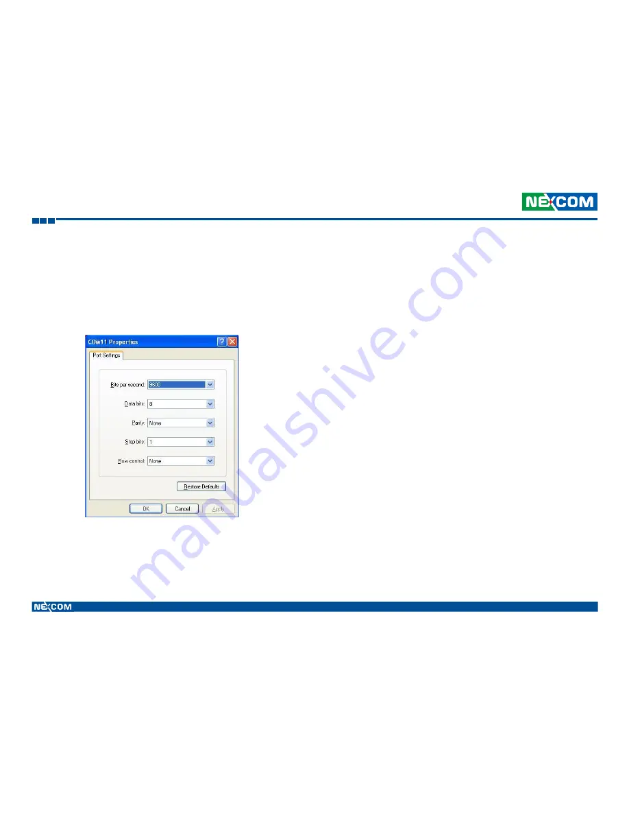
(6) Select these port settings, and click “OK”.

Содержание VMC 1000

Страница 1: ...NEXCOM International Co Ltd Published March 2014 www nexcom com NEXCOM International Co Ltd Mobile Computing Solutions Vehicle Mount Computer VMC 1000 User Manual ...

Страница 2: ...ation xiii Chapter 1 Product Introduction Overview 1 Key Features 1 Hardware Specifications 3 Getting to Know VTC 1000 7 Front Panel 7 Rear Panel 8 Lateral Side 9 I O Connectors 0 GPS Connector 10 Multi Connector 11 DC Power Connector 12 DC Power Cable Connector 12 SIM CARD Connector 13 USB Connector 13 Mic in Jack 14 Line out Jack 14 Chapter 2 Jumpers And Connectors Before You Begin 15 Precaution...

Страница 3: ...e Control Switch 27 POWER_IN Connector 28 Chapter 3 System Setup Installing a WLAN module or WWAN module 29 Appendix A I O Address Function I O Address Function 31 Appendix B Vehicle Power Management Setup Vehicle Power Management Setup 37 Appendix C Power Consumption Power Consumption 44 Appendix D SMS Wake up setting SMS Wake up setting 45 Appendix E RTC Wake up setting RTC Wake up setting 51 ...

Страница 4: ...es if it has a CE marking For computer systems to remain CE compliant only CE compliant parts may be used Maintaining CE compliance also requires proper cable and cabling techniques Copyright This publication including all photographs illustrations and software is protected under international copyright laws with all rights reserved No part of this manual may be reproduced copied translated or tra...

Страница 5: ...RoHS components and new manufacturing processes maintain the highest industry quality lev els for which NEXCOM are renowned The model selection criteria will be based on market demand Vendors and suppliers will ensure that all designed components will be RoHS compliant How to recognize NEXCOM RoHS Products For existing products where there are non RoHS and RoHS versions the suf fix LF will be adde...

Страница 6: ...M If the components were suspected as part of the problems please note clearly which components are included Otherwise NEXCOM is not responsible for the devices parts Customers are responsible for the safe packaging of defective products making sure it is durable enough to be resistant against further dam age and deterioration during transportation In case of damages occurred during transportation...

Страница 7: ...e surface cart or stand Follow all warnings and cautions in this manual When replacing parts ensure that your service technician uses parts spec ified by the manufacturer Avoid using the system near water in direct sunlight or near a heating device The load of the system unit does not solely rely for support from the rackmounts located on the sides Firm support from the bottom is highly necessary ...

Страница 8: ... greater than the volt age and current rating marked on the product 11 All cautions and warnings on the equipment should be noted 12 If the equipment is not used for a long time disconnect it from the power source to avoid damage by transient overvoltage 13 Never pour any liquid into an opening This may cause fire or electrical shock 14 Never open the equipment For safety reasons the equipment sho...

Страница 9: ...intenance to keep the unit clean use only approved cleaning prod ucts or clean with a dry cloth 3 CompactFlash Turn off the unit s power before inserting or removing a CompactFlash storage card Conventions Used in this Manual Warning Information about certain situations which if not ob served can cause personal injury This will prevent injury to your self when performing a task Caution Information...

Страница 10: ... 2 Chongde Rd Beitun Dist Taichung City 406 R O C Tel 886 4 2249 1179 Fax 886 4 2249 1172 Email sales nexcom com tw www nexcom com tw Japan NEXCOM Japan 9F Tamachi Hara Bldg 4 11 5 Shiba Minato ku Tokyo 108 0014 Japan Tel 81 3 5419 7830 Fax 81 3 5419 7832 Email sales nexcom jp com www nexcom jp com China NEXCOM China 2F Block 4 Venus Plaza Bldg 21 ZhongGuanCun Software Park No 8 Dongbeiwang West R...

Страница 11: ...l 44 1908 267121 Fax 44 1908 262042 Email sales uk nexcom eu www nexcom eu Shenzhen Office Room1707 North Block Pines Bldg No 7 Tairan Rd Futian Area Shenzhen 518040 China Tel 86 755 8332 7203 Fax 86 755 8332 7213 Email sales nexcom cn www nexcom cn Wuhan Office 1 C1804 1805 Mingze Liwan No 519 South Luoshi Rd Hongshan District Wuhan 430070 China Tel 86 27 8722 7400 Fax 86 27 8722 7400 Email sales...

Страница 12: ...listed in the following table Item P N Name Specification Qty 1 5044440135X00 THERMAL PAD E LIN 25x25x1mm K 5w mk TP 1800G 4 2 5044440303X00 THERMAL PAD FOR VMC1000 E LIN TP1800G 25x25x2mm K 5w mk 1 3 6023303701X00 N DB37 CABLE FOR VMC1000 SUNJET SL812822805 D SUB M37P SR L 300mm 1 4 60233PW236X00 N POWER DOCKING CABLE FOR VMC1000 SUNJET SL812822822 UL2464 20AWG L 130mm 1 5 60233SAM05X00 GPS ANTEN...

Страница 13: ...anual Preface Ordering Information The following provides ordering information for VMC 1000 VMC 1000 P N 10VC0100000X0 7 inch All in One Vehicle Mount Computer with Touch Screen and Smart Brightness Control and Intel Atom E640 1 0Ghz processor with 1GB DDR2 GPS module and GPS antenna ...

Страница 14: ...t Introduction Overview Key Features 7 WVGA TFT LCD with LED backlight Compact and fanless design Built in Intel Atom E640 1 0GHz processor Wake on RTC SMS GPS receiver on board VMC 1000 Front View VMC 1000 Rear View Variety wireless communication options Wide Range DC input from 6 36V Compliant with IP54 Certified by CE FCC e13 Mark ...

Страница 15: ... Intel Atom E640 it integrates the high resolution LCD with the brightness of 400 nits and 4 wire resistive touch sensor VMC 1000 does not compromise with its space to scarify its functional features It provides RS 232 422 485 USB 2 0 GPIO and LAN signal via DB37 connector to secure the cable simultaneously in the vehicle vibration Its mounting hole is compatible with VESA75 and can be installed i...

Страница 16: ...s Control Light Sensor 2 x LED indicators 2 x Built in Speakers 1W I O Interfaces Lateral Side 1 x Line in 1 x Line out 1 x USB 1 x SIM slot 1 x Power Button 1 x Reset Button Bottom Side 1 x DB9 male connector RS 232 1 x DB37 female connector 1x LAN 2x USB 1x RS232 1 x RS422 485 6 x GPIO 1 x CAN 6 36V Wide Range DC power input 1 x SMA connector for GPS antenna Expandable Storage 1 x mSATA Power Ma...

Страница 17: ...F Method 514 5 Category 20 Ground Vehicle Highway Truck Storage MIL STD 810F Method 514 5 Category 24 Integrity Test Shock with SSD Operating MIL STD 810F Method 516 5 Procedure I Trucks and semi trailers 20g Crash Hazard MIL STD 810F Method 516 5 Procedure V Ground equipment 75g Certifications CE approval FCC Class B e13 Mark Power Management Power on delay time is selectable by BIOS to disable a...

Страница 18: ...ly If the ignition is off the user can detect this status via the software If the ignition is turned on again and the power off delay is in progress VMC 1000 will cancel the delay function and will continue to operate normally If the ignition is turned on again and the power off delay ended VMC 1000 will shut down completely will power on again automatically If the ignition is turned off again and...

Страница 19: ...Copyright 2011 NEXCOM International Co Ltd All rights reserved 6 VMC 1000 User Manual Chapter 1 Product Introduction ...

Страница 20: ...t in light sensor will detect environmental brightness and adjust LCD brightness automatically Switching between Manual Mode and Auto Mode To toggle between Manual Mode and Auto Mode press and hold the or buttons for 4 seconds Getting to Know VMC 1000 Front View 3 Volume Control Audio volume can be adjusted in 8 levels using the buttons 4 LED PWR LED is turned on when VMD 1000 is powered on Mode L...

Страница 21: ...l rights reserved 8 VMC 1000 User Manual Chapter 1 Product Introduction 1 GPS antenna mounting 2 RS 232 Connector DB9 3 DB37 female connector 1x LAN 2x USB 1x RS232 1 x RS422 485 6 x GPIO 1x CAN 4 6 36V Wide Range DC power input Rear View 4 1 2 3 ...

Страница 22: ...l Co Ltd All rights reserved 9 VMC 1000 User Manual Chapter 1 Product Introduction 1 SIM slot 2 USB 2 0 1 1 3 Mic in 4 Line out Another side is power button and reset button3 Volume Control Getting to Know VMC 1000 Lateral Side 5 6 7 8 ...

Страница 23: ...ocation CN6 Connector size GPS SMA Connector 5 Pin Pin Definition 1 RF_IN_F MH1 GND MH2 GND MH3 GND MH4 GND RS232 Connector PIn Definition 1 SP_DCD_0 2 SP_RXD_0 3 SP_TXD_0 4 SP_DTR_0 5 CON0_GND 6 SP_DSR_0 7 SP_RTS_0 8 SP_CTS_0 9 SP_RI_0 Getting to Know VMC 1000 GPS Connector Connector location CN10 Connector size Male DSUB 9 PIN ...

Страница 24: ...P 20 LAN_M0N 2 LAN_M1P 21 LAN_M1N 3 LAN_M2P 22 LAN_M2N 4 LAN_M3P 23 LAN_M3N 5 L_GND 24 G_OUT1 6 G_IN1 25 G_OUT2 7 G_IN2 26 G_OUT3 8 G_IN3 27 USB_VCC5 9 USB_VCC5 28 HUSB_6N_R 10 HUSB_6P_R 29 HUSB_7N_R 11 HUSB_7P_R 30 RS422_TX 12 U_GND 31 RS422_TX 13 RS422_RX RS485_ 32 CANH 14 RS422_RX RS485_ 33 CANL 15 SP_RI_1 34 C_GND 16 SP_DCD_1 35 SP_RXD_1 17 SP_TXD_1 36 SP_RTS_1 18 SP_CTS_1 37 SP_DSR_1 19 SP_DT...

Страница 25: ...al Co Ltd All rights reserved 12 VMC 1000 User Manual Chapter 1 Product Introduction Pin Definition 1 V_IN 6 36V 2 IGNITION 3 GND DC Power connector Pin color Definition YEL HT Solder together for V_IN BLK GND DC Power cable connector ...

Страница 26: ...nual Chapter 1 Product Introduction Connector location CN5 Pin Definition C1 UIM_PWR2 C2 UIM_RST2 C3 UIM_CLK2 C5 GND C6 NC C7 UIM_DAT2 USB Connector SIM Card Reader Connector Connector location USB1 Connector size Single USB 4Pin Pin Definition 1 VCC 2 DATA USB_0N 3 DATA USB_0P 4 GND ...

Страница 27: ...Introduction Connector location CN7 Connector size EAR PHONE JACK PINK Pin Definition 1 FRONT_OUT_RC 2 LINE_OUTD 3 NC 4 FRONT_OUT_LC 5 ACON_GND 6 ACON_GND Line out Jack Mic in Jack Connector location CN8 Connector size EAR PHONE JACK GREEN Pin Definition 1 NC 2 MIC_JD 3 NC 4 MIC_OUT L 5 ACON_GND 6 ACON_GND ...

Страница 28: ...ower is off Ground yourself before touching any internal components by touching a metal object Static electricity can damage many of the electronic com ponents Humid environment tend to have less static electricity than dry environments A grounding strap is warranted whenever danger of static electricity exists Precautions Computer components and electronic circuit boards can be damaged by dischar...

Страница 29: ...pers ensure that the jumper caps are placed on the correct pins When the jumper cap is placed on both pins the jumper is short If you remove the jumper cap or place the jumper cap on just one pin the jumper is open Refer to the illustrations below for examples of what the 2 pin and 3 pin jumpers look like when they are short on and open off Two Pin Jumpers Open Left and Short Right Three Pin Jumpe...

Страница 30: ...hapter 2 Jumpers and Connectors Locations of the Jumpers and Connectors The figure below is the main board which is the board used in the VMC 1000 system It shows the locations of the jumpers and connectors CN2 CN3 CN4 J12 SW1 SW2 CN9 CN10 J5 CN6 CN5 CN7 CN8 USB1 J7 J3 J6 J10 J8 J9 CN1 J2 ...

Страница 31: ...1 RX3 11 GND1 2 RX3 12 RX1 3 NC 13 RX1 4 FRC 14 GND0 5 GND3 15 RX0 6 RXC 16 RX0 7 RXC 17 LR default 1 8 GND2 18 UD default 0 9 RX2 19 VCC_IN1 10 RX2 20 VCC_IN2 Panel Connector Connector size 1 25mm WAFER 20P Connector location J7 J7 LCD_CON_20P NC 3 RX3 1 RX3 2 RX0 16 VCC_IN2 20 VCC_IN1 19 GND3 5 RXC 6 FRC 4 GND2 8 RX2 9 RXC 7 GND1 11 RX1 12 RX2 10 GND0 14 RX0 15 RX1 13 MH1 MH2 LR 17 UD 18 ...

Страница 32: ...ctor location CN1 FPC CON 1mm FPC_1X4P 1mm CN1 1 1 2 2 3 3 4 4 MH1 MH1 MH2 MH2 PIN Definition 1 TOUCH_XL 2 TOUCH_YD 3 TOUCH_XR 4 TOUCH_YU Button Sensor LED Connector Connector size 1mm Wafer 10 Pin180 O Connector location J5 PIN Definition 1 LS_D 2 LS_A 3 KEY_V 4 KEY_V 5 KEY_BL 6 KEY_BL 7 BOT_M_N 8 AUTO_BL_LED 9 POWER_LED 10 GND J5 WAFER M 180 1mm 1 2 3 MH1 MH2 4 8 7 6 5 10 9 ...

Страница 33: ...ocation J2 J6 J2 PIN Definition 1 FRONT_A_R _R 2 FRONT_A_R _R J2 WAFER M 90 1mm 1 2 MH1 MH2 J6 PIN Definition 1 FRONT_A_L _R 2 FRONT_A_L _R 8051 Download Connector Connector size 2 54mm PIN HEADER 5Pin 180 O Connector location JP3 JP5 JP3 PIN Definition 1 V3 3ALW 2 C2D_1 3 MRST_1 4 C2CK_1 5 GND JP3 PIN M 180 2 54mm 1 2 3 4 5 JP5 PIN Definition 1 V_MCU2 2 C2D_2 3 MRST_2 4 C2CK_2 5 GND ...

Страница 34: ...er 2 Jumpers and Connectors RTC Control Connector JP1 PIN Definition 1 RTCRSTN 2 RTC_CLR 3 RTCGND JP1 PIN M 180 2 54mm 1 2 3 RTC Battery Connector Connector size WAFER M 180 1 25mm Connector location J4 J4 PIN Definition 1 GND 2 VBAT1 MH1 GND MH2 GND J4 WAFER M 180 1 25mm G1 MH1 G2 MH2 1 1 2 2 ...

Страница 35: ...rs Backlight Connector power Connector size 1 25mm Wafer 2 Pin 90 O Connector location J10 J10 PIN Definition 1 GND 2 Panel_backlight J10 WAFER M 90 1 25mm 1 2 MH1 MH2 Backlight Connector data Connector size 1mm Wafer 2Pin 90 O Connector location J8 J8 PIN Definition 1 Brightness 2 BK_EN J8 WAFER M 90 1mm 1 2 MH1 MH2 ...

Страница 36: ... Connector location J3 J3 PIN Definition 1 CCD_PWR 2 HUSB_9N 3 HUSB_9P 4 GND 5 CCD_EN_L 6 NC J3 WAFER M 90 1mm 1 2 3 MH1 MH2 4 5 6 PORT 80 Connector Connector size 1mm Wafer 10 Pin 90 O Connector location J9 J9 PIN Definition 1 VCC3_S 2 VCC3_S 3 LPC_AD0 4 LPC_AD1 5 LPC_AD2 6 LPC_AD3 7 LPC_FRAME 8 LPC_CLK2 9 SIO_RST 10 GND J9 WAFER M 90 1mm 1 2 3 MH1 MH2 4 5 6 10 9 8 7 ...

Страница 37: ...NI PCIE CON Ver 1 2 CN2 REV1 51 REV2 49 REV3 47 REV4 45 GND14 43 3 3VSB_5 41 3 3VSB_4 39 GND13 37 GND0 35 PETp0 33 PETn0 31 GND2 29 GND3 27 PERp0 25 PERn0 23 GND4 21 REV9 UIM_C4 19 REV10 UIM_C8 17 GND5 15 REFCLK 13 REFCLK 11 GND6 9 CLKREQ 7 COEX2 5 COEX1 3 WAKE 1 3 3VSB_2 52 GND7 50 1 5V_1 48 LED_WPAN 46 LED_WLAN 44 LED_WWAN 42 GND8 40 USB_D 38 USB_D 36 GND9 34 SMBDAT 32 SMBCLK 30 1 5V_2 28 GND10 ...

Страница 38: ...VS 3 NC 29 GND 4 GND 30 SMB_CLK 5 NC 31 mPCIE_TX_N 6 D15VS 32 SMB_DATA 7 CLKREQ 33 mPCIE_TX_P 8 NC 34 GND 9 GND 35 GND 10 NC 36 USB_IN 11 MC_PCIE_CLK_N 37 GND 12 NC 38 USB_IP 13 MC_PCIE_CLK_P 39 3 3B_MINI 14 NC 40 GND 15 GND 41 3 3B_MINI 16 NC 42 NC 17 NC 43 GND 18 GND 44 LED_WLAN 19 NC 45 NC PIN Definition PIN Definition 20 MINICARD1_DIS 46 NC 21 GND 47 NC 22 WLAN_RESET 48 D15VS 23 mPCIE_RX_N 49 ...

Страница 39: ...29 GND 4 GND 30 NC 5 NC 31 NC 6 NC 32 SMS_RI_3 5G 7 UMTS_GND 33 UMTS_RESET 8 UIM_PWR2 34 GND 9 GND 35 GND 10 UIM_DAT2 36 USB_3N 11 VCC_MSM26_DIG 37 GND 12 UIM_CLK2 38 USB_3P 13 NC 39 3 3A_MINI 14 UIM_RST2 40 GND 15 GND 41 3 3A_MINI 16 NC 42 3 5G_LED 17 NC 43 GND 18 GND 44 NC 19 NC 45 NC PIN Definition PIN Definition 20 3 5G_DIS 46 NC 21 GND 47 NC 22 NC 48 NC 23 NC 49 MINI_RXD_PCMDOUT_NC 24 NC 50 G...

Страница 40: ...L Download Connector Connector size 2 54mm PIN HEADER 6Pin 180 O Connector location JP2 PIN Definition 1 V3P3_G 2 GND 3 TCK 4 TDO 5 TDI 6 TMS JP2 PIN M 180 2 54mm 1 2 3 4 5 6 Input Voltage Control Switch Connector size 2x2 DIP SWITCH 180 O Connector location SW3 PIN Definition 1 POWERSW 2 12V24V 3 GND 4 GND ON SW3 1 2 3 4 ...

Страница 41: ...ors POWER_IN Connector Connector size 2 5mm Wafer 6 Pin 180 O Connector location J12 PIN Definition 1 V_IN 2 V_IN 3 V_IN 4 V_IN 5 V_IN 6 V_IN 7 V_IN 8 IGNITION J12 WAFER M 180 1 0mm 3 MH1 MH2 4 8 7 6 10 9 11 12 5 13 14 15 1 2 16 PIN Definition 9 IGNITION 10 V_GND 11 V_GND 12 V_GND 13 V_GND 14 V_GND 15 V_GND 16 V_GND ...

Страница 42: ...The Mini PCI Express slot shown below is used to install a WLAN module or 3 5G commu nication module such as GPRS UMTS or HSDPA module CAUTION CAUTION CAUTION Prior to removing the chassis cover make sure the unit s power is off and disconnected from the power sources to prevent electric shock or system damage 1 Remove these screws and put them in a safe place for later use For 3 5G module For WLA...

Страница 43: ... 4 Before you install the rear cover please check the all thermal pads are on the heatsink System Setup 3 Insert the module into the Mini PCI Express slot at a 45 degrees angle until the gold plated connector on the edge of the module completely disappears inside the slot And then attach RF cable to the module ...

Страница 44: ...ress Function GPIO LED UMTS LED Ignition Status I O port 0EE0H Bit Function Description Bit 0 GPIO LED VMC1000 UNUSED 0 OFF 1 ON Bit 1 UMTS LED VMC1000 UNUSED 0 LED for Wireless 1 LED for 3 5G and Wireless Bit 2 Ignition read only 0 OFF 1 ON Bit 3 Status of Car Battery 0 Car Battery is OK 1 Car Battery is Low voltage for default setting ...

Страница 45: ... Disable 1 Enable Bit 1 WLAN module 0 Disable 1 Enable Bit 2 RESERVED Bit 3 RESERVED Bit 4 Wake on 3 5G module 0 Disable 1 Enable Bit 5 Wake on RTC module 0 Disable 1 Enable Bit 2 1 0 Time Setting Bit 2 0 Time sec 000 1 001 2 010 4 011 8 100 16 101 32 110 64 111 128 WDT I O port 0EE5H Bit Function Description Bit 3 WDT Disable Enable 0 Disable 1 Enable Auto clear WDT timer when reading writing I O...

Страница 46: ...11 10 min 100 30 min 101 1 hour 110 6 hour 111 18 hour Delay On Time Setting Bit5 6 Function Description 000 10 sec 001 30 sec 010 1 min 011 5 min 100 10 min 101 15 min 110 30 min 111 1 hour Only set by switch on motherboard read only Bit1 0 Input Voltage 12V 00 Startup Shutdown 11 5V 10 5V 01 Startup Shutdown 12V 11V 10 Startup Shutdown 12 5V 11V 11 Startup Shutdown 12 5V 11 5V When input voltage...

Страница 47: ... Command I O port 0EE9H Enable byte AA Restart the Setup Command Data End byte Delay time Startup Shutdown voltage setting 55 Using end byte to tell the data flow end Bit1 0 Input Voltage 24V 00 Startup Shutdown 23V 21V 01 Startup Shutdown 24V 22V 10 Startup Shutdown 25V 22V 11 Startup Shutdown 25V 23V When input voltage 24V ...

Страница 48: ...binary I O port 0EEDH clock Timer Bit0 7 the minute value binary I O port 0EEEH User setting Time Bit0 7 the hour value binary I O port 0EEFH User setting Time Bit0 7 the minute value binary Onboard Module Disable Enable 1 I O port 0EEAH Bit Function Description Bit 0 Status of RS422 485 MODULE1 0 RS 422 1 RS 485 GAL Download control I O port 0EEBH Enable byte AA Restart the Setup Command ...

Страница 49: ...ht 2011 NEXCOM International Co Ltd All rights reserved 36 VMC 1000 User Manual Appendix A I O Address Function GPIO I O port 0EE4H Default Value 0x38H Bit Function Description Bit 0 2 GPO 0 2 Bit 3 5 GPI 0 2 ...

Страница 50: ...All rights reserved 37 VMC 1000 User Manual Appendix B Vehicle Power Management Setup Appendix B Vehicle Power Management Setup External Power Output Setting External 12V and 5V Turn Off Simultaneously External 12V and 5V Turn On Simultaneously ...

Страница 51: ...OM International Co Ltd All rights reserved 38 VMC 1000 User Manual Appendix B Vehicle Power Management Setup Vehicle Power Management Setup External 5V Turn On Only External 12V Turn On Only External Power Output Setting ...

Страница 52: ... the input voltage setting is 12V set the startup voltage to 11 5V and the shutdown voltage to 10 5V If the input voltage setting is 12V set the startup voltage to 12V and the shutdown voltage to 11V If the input voltage setting is 12V set the startup voltage to 12 5V and the shutdown voltage to 11 5V If the input voltage setting is 12V set the startup voltage to 12 5V and the shutdown voltage to ...

Страница 53: ... 2 If the input voltage setting is 24V set the startup voltage to 23V and the shutdown voltage to 21V If the input voltage setting is 24V set the startup voltage to 24V and the shutdown voltage to 22V If the input voltage setting is 24V set the startup voltage to 25V and the shutdown voltage to 22V If the input voltage setting is 24V set the startup voltage to 25V and the shutdown voltage to 23V ...

Страница 54: ...Co Ltd All rights reserved 41 VMC 1000 User Manual Appendix B Vehicle Power Management Setup Vehicle Power Management Setup Startup and Shutdown Voltage Setting 4 If the input voltage setting is 6v 36V ignore the startup shutdown setting ...

Страница 55: ...ights reserved 42 VMC 1000 User Manual Appendix B Vehicle Power Management Setup Vehicle Power Management Setup Enable Power on Delay Delay time can be set at 10sec 30sec 1min 5min 10min 15min 30min 1hour Disable Power on Delay Power on Delay Setting ...

Страница 56: ...hts reserved 43 VMC 1000 User Manual Appendix B Vehicle Power Management Setup Vehicle Power Management Setup Disable Power off Delay Power on Delay Setting Enable Power off Delay Delay time can be set at 20sec 1min 5min 10min 30min 1hour 6hour 18hour ...

Страница 57: ...C1000 with 32GB mSATA and 3 5G WWAN module Windows XP Burn in Software Version 5 0 Test Condition Room temperature Power supply graduation 12V 5A Test Procedure 1 Start of all function at DUT and measure power consumption 2 Get system into suspend mode and measure power consumption Unit Idle Mode 100 Burn in Mode S3 S4 S5 DUT 1 1 3A 1 33A 148mA 12mA 12mA DUT 2 1 33A 1 35A 72mA 56 7mA 56 7mA Device...

Страница 58: ... Setting of the main menu screen 2 Select Module Management Utilizing sleep mode on the Serra MC8970V 3 5G module and allowing for remote wake up via SMS The specification of MC8970V and AT command reference are in the CD ROM Two process to setting the SMS wake up mode for VTC1000 Please do the following to set it up 3 Change the value to Enable for 3 5G Module and Wake On 3 5G Module ...

Страница 59: ...you have finished with the Setup press ESC to go back to the main menu and then press Enter on Save Changes and Reset B Module setting 1 Go into the System applet in the Windows Control Panel and access Device Manager 2 In the Ports COM LPT section you will find a port labeled Sierra Wireless AT Command Port UMTS followed by a COM port number such as COM11 ...

Страница 60: ...r version of Windows and how it was installed you can launch the program by selecting Start Programs Accessories Communications HyperTerminal 4 Enter any name and select and icon in the Connection Description windows and click OK 5 Select the COM port to which the modem is connected use COM11 in this sample in the Connect using field and click OK 6 Select these port settings and click OK ...

Страница 61: ...ng 7 Enter the at entercnd A710 and the response would be OK 8 Enter the at mapuart 1 and the response would be OK 9 After completed the AT commands restart your computer 10 Repeat the process 3 and 4 11 Select the COM port to which the modem is connected use COM6 in the Connect using field and click OK 12 Select these port settings and click OK ...

Страница 62: ...5 Enter the at wwkup and the response would be WWKUP 04 and OK It mean the setting is completed C Return the default setting 1 Lunch HyperTerminal Depending on your version of Windows and how it was installed you can launch the program by selecting Start Programs Accessories Communications HyperTerminal 2 Select the COM port to which the modem is connected use COM6 in the Connect using field and c...

Страница 63: ...d All rights reserved 50 VMC 1000 User Manual Appendix D SMS Wake up setting Appendix D SMS Wake up setting 3 Enter the at entercnd A710 and the response would be OK 4 Enter the at mapuart 0 and the response would be OK 5 Restart your computer ...

Страница 64: ...td All rights reserved 51 VMC 1000 User Manual Appendix E RTC Wake up setting Appendix E RTC Wake up setting 1 Press Enter on BIOS Setting of the main menu screen 2 Select Module Management 3 Change the value to Enable for Wake On RTC Module ...

Страница 65: ... Appendix E RTC Wake up setting 4 You can key in the value for User Setting Hour 0 23 and User Set ting Minute 0 59 5 After you have finished with the Setup press ESC to go back to the main menu and then press Enter on Save Changes and Reset Note SMS wake up function only works in S3 S4 or S5 mode and the ignition off ...

Отзывы: