


Copyright © 2023 NexCOBOT Co., Ltd. All Rights Reserved.
16
NEX 813 User Manual
Chapter 2: Jumpers and Connectors
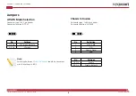
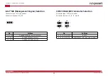
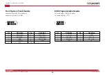
Front/System Panel Header
Connector type: 2x5 10-pin header
Connector location: F_PANEL
Pin
Definition
Pin
Definition
1
2
3
HDD_LED-
4
PWR_LED-
5
GND
6
PWR_BTN#
7
RSTCON#
8
GND
9
NC
10
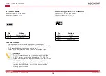
BIOS Programmable Header
Connector type: 2x4 8-pin header
Connector location: SPI_1
Pin
Definition
Pin
Definition
1
+3V_SPI
2
GND
3
SPI_CS#
4
SPI_CLK
5
SPI_MISO
6
SPI_MOSI
7
NC
8
NC
2
10
1 9
2
8
1 7