4.
Alignment and Measurement
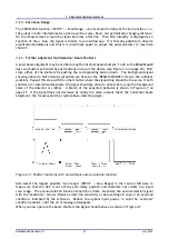
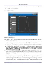
Figure 4.3.: View of alignment window in collinear and non-collinear mode (visible laser used for
demonstration purpose).
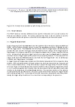
Figure 4.4.:
Pulse
Scout2
optical head right side view with beam distance screw
The beam distance, once the two re ections are aligned properly, can be changed to the collinear
mode in order to maximize the autocorrelation signal on the Control Software. The autocorrelation
signal will increase while changing from non-collinear to collinear mode.
If one has trouble nding the autocorrelation trace, turn the screw (see Figure 4.4) all the way in for
collinear operation (see Figure 4.3). In collinear mode, a signal increase from the autocorrelator
can be seen if the crystal is aligned at the proper angle, even if the two replica beams do not
overlap temporally. Hence, due to the fewer variables involved, it is best to use the collinear
con guration to begin with the optimization of the autocorrelation trace.
Once the optical assembly is coarsely aligned, it should be xed to the table with the provided foot
clamps.
Adjust the input beam in horizontal and vertical position in order to increase the autocorrelation
signal in comparison to the background signal. The variable alignment aperture can now be moved
into the measurement position (see Figure 4.2 on page 23).
Pulse
Scout2 Version 1.1
24
July 2015


